
Fundamentals of Electric Circuits
6th Edition
ISBN: 9780078028229
Author: Charles K Alexander, Matthew Sadiku
Publisher: McGraw-Hill Education
expand_more
expand_more
format_list_bulleted
Concept explainers
Videos
Textbook Question
Chapter 2, Problem 58P
The 150 W tight bulb in Fig. 2.122 is rated at 110 volts. Calculate the value of Vs to make the light bulb operate at its rated conditions.
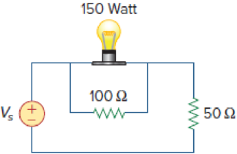
Figure 2.122
Expert Solution & Answer
Want to see the full answer?
Check out a sample textbook solution
Students have asked these similar questions
1. Using KVL and/or KCL, determine the unknown current and voltage for each resistor for the circuit
given in Figure 2.7. Verify that the total voltage is equal to the supply voltage.
V = 12V
R- 120n
R:- 4.7kn
R= 1.5kn
Figure 2.7
2. Using KVL and/or KCL, determine the unknown current and voltage for each resistor for the circuit
given in Figure 2.8.
V= 10V
R: = 3.3kn
R;= 22kn
R = 1.5kn
Figure 2.8
3. Using KVL and/or KCL, determine the unknown current and voltage for each resistor for the circuit
given in Figure 2.9 (2).
RI
V- 15V
R: = 1200
R: = 4.7kn
R = 1.5kn
R= 4.7kn
Figure 2.9
4. Determine the equivalent resistance seen from the voltage supply for the circuits given in Step 1,
Step 2 and Step 3.
Q2: Calculate the reading that would be observed on a moving-iron ammeter when it is
measuring the current in the circuit shown in Figure
Current
ot
27
2. Using KVL and/or KCL, determine the unknown current and voltage for each resistor for the circuit
given in Figure 2.8.
Vs= 10V
R: = 3.3kn
R; = 22kn
R = 1.5kn
Figure 2.8
Chapter 2 Solutions
Fundamentals of Electric Circuits
Ch. 2.2 - The essential component of a toaster is an...Ch. 2.2 - For the circuit shown in Fig. 2.9, calculate the...Ch. 2.2 - A resistor absorbs an instantaneous power of 30...Ch. 2.3 - How many branches and nodes does the circuit in...Ch. 2.4 - Find v1 and v2 in the circuit of Fig. 2.22. Figure...Ch. 2.4 - Find vx and vo in the circuit of Fig. 2.24. Figure...Ch. 2.4 - Find vo and io in the circuit of Fig. 2.26. Figure...Ch. 2.4 - Find the current and voltages in the circuit shown...Ch. 2.6 - By combining the resistors in Fig.2.36, find Req....Ch. 2.6 - Find Rab for the circuit in Fig.2.39. Figure 2.39...
Ch. 2.6 - Calculate Geq in the circuit of Fig.2.41. Figure...Ch. 2.6 - Find v1 and v2 in the circuit shown in Fig. 2.43....Ch. 2.7 - Transform the wye network in Fig. 2.51 to a delta...Ch. 2.7 - For the bridge network in Fig. 2.54, find Rab and...Ch. 2.8 - Refer to Fig. 2.55 and assume there are six light...Ch. 2.8 - Following the ammeter setup of Fig. 2.61. design...Ch. 2 - The reciprocal of resistance is: (a) voltage (b)...Ch. 2 - Prob. 2RQCh. 2 - Prob. 3RQCh. 2 - The maximum current that a 2W, 80 k resistor can...Ch. 2 - Prob. 5RQCh. 2 - The current I in the circuit of Fig. 2.63 is: (a)...Ch. 2 - The current I0 of Fig. 2.64 is: (a) 4 A (b) 2 A...Ch. 2 - In the circuit in Fig. 2.65, V is: (a) 30 V (b) 14...Ch. 2 - Which of the circuit in Fig. 2.66 will give you...Ch. 2 - In the circuit of Fig. 2.67, a decrease in R3...Ch. 2 - Design a problem, complete with a solution, to...Ch. 2 - Find the hot resistance of a light bulb rated 60...Ch. 2 - A bar of silicon is 4 cm long with a circular...Ch. 2 - (a) Calculate current i in Fig. 2.68 when the...Ch. 2 - For the network graph in Fig. 2.69. find the...Ch. 2 - In the network graph shown in Fig. 2.70, determine...Ch. 2 - Determine the number of branches and nodes in the...Ch. 2 - Design a problem, complete with a solution, to...Ch. 2 - Find i1, i2, and i3 in Fig. 2.73. Figure 2.73 For...Ch. 2 - Determine i1 and i2 in the circuit of Fig. 2.74....Ch. 2 - In the circuit of Fig. 2.75, calculate V1 and V2....Ch. 2 - In the circuit in Fig. 2.76, obtain v1, v2, and...Ch. 2 - For the circuit in Fig. 2.77, use KCL to find the...Ch. 2 - Given the circuit in Fig. 2.78, use KVL to find...Ch. 2 - Calculate v and ix in the circuit of Fig. 2.79....Ch. 2 - Determine Vo in the circuit in Fig. 2.80. Figure...Ch. 2 - Obtain v1 through v3 in the circuit of Fig. 2.81....Ch. 2 - Find I and V in the circuit of Fig. 2.82. Figure...Ch. 2 - From the circuit in Fig. 2.83, find I, the power...Ch. 2 - Determine io in the circuit of Fig. 2.84. Figure...Ch. 2 - Find Vx in the circuit of Fig. 2.85. Figure 2.85...Ch. 2 - Find Vo in the circuit in Fig. 2.86 and the power...Ch. 2 - In the circuit shown in Fig. 2.87, determine Vx...Ch. 2 - For the circuit in Fig. 2.88, find Vo/Vs in terms...Ch. 2 - For the network in Fig. 2.89, find the current,...Ch. 2 - For the circuit in Fig. 2.90, io = 3 A. Calculate...Ch. 2 - Calculate Io in the circuit of Fig. 2.91. Figure...Ch. 2 - Design a problem, using Fig. 2.92, to help other...Ch. 2 - All resistors (R) in Fig. 2.93 are 10 each. Find...Ch. 2 - For the circuit in Fig. 2.95, determine i1 to i5....Ch. 2 - Find i1 through i4 in the circuit in Fig. 2.96....Ch. 2 - Obtain v and i in the circuit of Fig. 2.97. Figure...Ch. 2 - Using series/parallel resistance combination, find...Ch. 2 - Calculate Vo and Io in the circuit of Fig. 2.99....Ch. 2 - Find i and Vo in the circuit of Fig. 2.100. Figure...Ch. 2 - Given the circuit in Fig. 2.101 and that the...Ch. 2 - Find Req and io in the circuit of Fig. 2.102....Ch. 2 - Evaluate Req looking into each set of terminals...Ch. 2 - For the ladder network in Fig. 2.104, find I and...Ch. 2 - If Req = 50 in the circuit of Fig. 2.105, find R....Ch. 2 - Reduce each of the circuits in Fig. 2.106 to a...Ch. 2 - Calculate the equivalent resistance Rab at...Ch. 2 - For the circuits in Fig. 2.108, obtain the...Ch. 2 - Find the equivalent resistance at terminals a-b of...Ch. 2 - Find I in the circuit of Fig. 2.110. Figure 2.110Ch. 2 - Find the equivalent resistance Rab in the circuit...Ch. 2 - Convert the circuits in Fig. 2.112 from Y to ....Ch. 2 - Transform the circuits in Fig. 2.113 from to Y....Ch. 2 - Design a problem to help other students better...Ch. 2 - Obtain the equivalent resistance at the terminals...Ch. 2 - For the circuit shown in Fig. 2.116, find the...Ch. 2 - Obtain the equivalent resistance Rab in each of...Ch. 2 - Consider the circuit in Fig. 2.118. Find the...Ch. 2 - Calculate I0 in the circuit of Fig. 2.119. Figure...Ch. 2 - Determine V in the circuit of Fig. 2.120. Figure...Ch. 2 - Find Req and I in the circuit of Fig. 2.121....Ch. 2 - The 150 W tight bulb in Fig. 2.122 is rated at 110...Ch. 2 - If the three bulbs of Prob. 2.59 are connected in...Ch. 2 - As a design engineer, you are asked to design a...Ch. 2 - Prob. 62PCh. 2 - If an ammeter with an internal resistance of 100 ...Ch. 2 - The potentiometer (adjustable resistor) Rx in Fig....Ch. 2 - Design a circuit that uses a dArsonval meter (with...Ch. 2 - A 20-k/V voltmeter reads 10 V full scale. (a) What...Ch. 2 - (a) Obtain the voltage Vo in the circuit of Fig....Ch. 2 - (a) Find the current I in the circuit of Fig....Ch. 2 - A voltmeter used to measure Vo in the circuit in...Ch. 2 - (a) Consider the Wheatstone bridge shown in Fig....Ch. 2 - Figure 2.131 represents a model of a solar...Ch. 2 - Find Vo in the two-way power divider circuit in...Ch. 2 - An ammeter model consists of an ideal ammeter in...Ch. 2 - The circuit in Fig. 2.134 is to control the speed...Ch. 2 - Find Rab in the four-way power divider circuit in...Ch. 2 - Repeat Prob. 2.75 for the eight-way divider shown...Ch. 2 - Suppose your circuit laboratory has the following...Ch. 2 - In the circuit in Fig. 2.137, the wiper divides...Ch. 2 - Prob. 79CPCh. 2 - A loudspeaker is connected to an amplifier as...Ch. 2 - For a specific application, the circuit shown in...Ch. 2 - The pin diagram of a resistance array is shown in...Ch. 2 - Two delicate devices are rated as shown in Fig....
Knowledge Booster


Learn more about
Need a deep-dive on the concept behind this application? Look no further. Learn more about this topic, electrical-engineering and related others by exploring similar questions and additional content below.Similar questions
- 2. The internal resistance of the battery is 0.3 2. Find I, I1 and voltmeter readings V₁ and V₂ for the circuit shown in Figure 2. Ans.: I = 1.35 A, I₁ = 0.34 A, V₁ = 3.7 V, and V2 = 16.9 V. 7.115 20 V, 0.392 I 20 W 822 w ¾602 Figure 2. 792 w 1022 W 11 www 122arrow_forward2. Using KCL, find the unknown currents shown in the figure 2. 2 A 7A 3A Is 4 A Figure 2arrow_forward3. Compared to a voltmeter, the ammeter in Fig. 2.1 is:A. Drawn differently and connected differently B. Drawn the same and connected differently C. Drawn differently and connected the sameD. Drawn the same and connected the samearrow_forward
- 1. In the basic electrical cireuit given in Figure 1; a) Find the voltage and current passing through 600 resistor. (All mathematical calculations will be shown step by step) b) Make the necessary connection by drawing for the measurement of the current flowing through the 400 resistor using the multimeter given on the side. (You can indicate the measuring point with an arrow) 000.0 40 0 60 Q 120 V COM Figure 1. Basic Electrical Circuit Voltage: Current: >Oarrow_forwardThe power rating of a light bulb is the power it dissipates when connected across a 120 volt potential difference. What is the resistance, and current draw of: (b) a 30 W florescent bulb ? (2 and A)arrow_forward8. A light bulb, having a tungsten-filament, draws 2.85 A at 220 V when running at normal condition. The cold resistance of the filament is 18 N at 25 °C. The temperature coefficient of resistance is 0.00355 /ºC at 17 °C. Determine the temperature rise of the bulb when running at normal condition. gulor bus bar made of aluminu L1ain bararrow_forward
- Q2. The output power of a solar PV module is 100 Watts. The number of cells in the module is 48. Estimate the following: L Total output voltage i. Total output current iii. Total area of module iv. Power output of one PV cell Time Tibelarrow_forwardThe potential at the terminals of the battery falls from 9 V on open circuit to 6 volts when a resistor of 10 ohms is connected across its terminals. What is the internal resistance of the battery. O 5 ohms O 4 ohms O 3 ohms O2 ohmsarrow_forward2. Figure 1 shows an electric circuit with a battery with an emf (E), internal resistance r = 0.05 N and a load resistance composed of three resistors. A current of 2.1 A flows through the internal resistor, r. a) Calculate equivalent resistance of load resistors. b) Calculate emf, E. c) Calculate voltage across 5 N resistor, US UE d) Calculate current through15 N resistor, $150 Figure 1 e) Calculate power dissipated in the internal resistor. [*arrow_forward
- A spring controlled moving iron voltmeter draws a current of 1 mA for full scale value of 100 V. If it draws a current of 0.5 mA, the meter reading is a) 25 V. b) 50 V. c) 100 V. d) 200 V.arrow_forward2. 5. 1. The maximum measurable voltage on Range B is Page 2: 100 micro A, 1 k ohms Page 3: Range A R3 R2 R1 3. 300k ohms 100 k ohms 99 k ohms Range B Page 4: Range C Page 5: O 20.0 V O 10.1 V age 6: O 30.1 V O 10.0 V ge 7: Previous Page Next Page Page 11 of 70 ge 8: Submit Quiz 56 of 70 questions saved F 10 F 11 F 12arrow_forward2. In Figure, the battery voltage is V = 65 volts, and the values of the resistances, in ohms, are 38, 17, and 27, as shown. Find: (a) Total resistance seen by the battery, (b) Current measured by the ammeters shown in the figure, V= 65 V 38 2 170 27 2arrow_forward
arrow_back_ios
SEE MORE QUESTIONS
arrow_forward_ios
Recommended textbooks for you
 Introductory Circuit Analysis (13th Edition)Electrical EngineeringISBN:9780133923605Author:Robert L. BoylestadPublisher:PEARSON
 Delmar's Standard Textbook Of ElectricityElectrical EngineeringISBN:9781337900348Author:Stephen L. HermanPublisher:Cengage Learning
 Programmable Logic ControllersElectrical EngineeringISBN:9780073373843Author:Frank D. PetruzellaPublisher:McGraw-Hill Education
 Fundamentals of Electric CircuitsElectrical EngineeringISBN:9780078028229Author:Charles K Alexander, Matthew SadikuPublisher:McGraw-Hill Education
 Electric Circuits. (11th Edition)Electrical EngineeringISBN:9780134746968Author:James W. Nilsson, Susan RiedelPublisher:PEARSON
 Engineering ElectromagneticsElectrical EngineeringISBN:9780078028151Author:Hayt, William H. (william Hart), Jr, BUCK, John A.Publisher:Mcgraw-hill Education,
Introductory Circuit Analysis (13th Edition)
Electrical Engineering
ISBN:9780133923605
Author:Robert L. Boylestad
Publisher:PEARSON
Delmar's Standard Textbook Of Electricity
Electrical Engineering
ISBN:9781337900348
Author:Stephen L. Herman
Publisher:Cengage Learning
Programmable Logic Controllers
Electrical Engineering
ISBN:9780073373843
Author:Frank D. Petruzella
Publisher:McGraw-Hill Education
Fundamentals of Electric Circuits
Electrical Engineering
ISBN:9780078028229
Author:Charles K Alexander, Matthew Sadiku
Publisher:McGraw-Hill Education
Electric Circuits. (11th Edition)
Electrical Engineering
ISBN:9780134746968
Author:James W. Nilsson, Susan Riedel
Publisher:PEARSON
Engineering Electromagnetics
Electrical Engineering
ISBN:9780078028151
Author:Hayt, William H. (william Hart), Jr, BUCK, John A.
Publisher:Mcgraw-hill Education,
Star Delta Starter Explained - Working Principle; Author: The Engineering Mindset;https://www.youtube.com/watch?v=h89TTwlNnpY;License: Standard Youtube License