
Fundamentals of Electric Circuits
6th Edition
ISBN: 9780078028229
Author: Charles K Alexander, Matthew Sadiku
Publisher: McGraw-Hill Education
expand_more
expand_more
format_list_bulleted
Videos
Textbook Question
Chapter 2, Problem 8P
Design a problem, complete with a solution, to help other students better understand Kirchhoff’s Current Law. Design the problem by specifying values of ia, ib, and ic, shown in Fig. 2.72, and asking them to solve for values of i1, i2, and i3. Be careful to specify realistic currents.
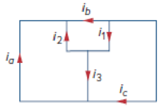
Figure 2.72
Expert Solution & Answer
Want to see the full answer?
Check out a sample textbook solution
Students have asked these similar questions
answer as soon
C) Figure Q2(c) shows a simple electronic circuit. A recently graduated engineering student from eau has been tasked by his Senior Engineer to determine the equivalent circuit between Terminal A and B. Please help him to analyze and find the equivalent resistance using delta-wye transformation
Use the following constants if necessary.
Coulomb constant, k = 8.987 x 10° N - m² /C2. Vacuum permitivity, co = 8.854 x 10 12 F/m. Magnetic Permeability of vacuum,
Ho = 12.566370614356 x 10-' H/m. Magnitude of the Charge of one electron, e = -1.60217662 × 10⁻¹⁹ C. Mass of one electron,
me = 9.10938356 x 10 31 kg. Unless specified otherwise, each symbol carries their usual meaning. For example, µC means micro coulomb.
a
R5
R3
e
R9
R,
R6
R8
Ry
K
Suppose you have the following circuit diagram. Here R1 =1.1 kN, R2 = 3.3 kN, R3 = 2.2 kN, R4 = 22 kN, R5 = 22 kN, Rg = 11 kN, R7 = 11 kN,
Rg = 11 kN, R9 = 1.1 kN are the resistances on the circuit where kN stands for kilo ohm. The electromotive forces of the batteries are & = 5 volts and
Ez = 3 volts.
a) Calculate Rik. the resistance equivalent to R5, Re, R7, Rg and R9 between the terminals b and k.
Value of Rhk
Give your answer to at least two significance digits.
Ω
b) Calculate the current through R1.
(Note that the a,b,c,d are branches)1. Measure and record the potential difference for the following branches. Be mindful of the algebraic sign.
a-b
a-c
b-c
c-d
a-d
b-d
And using the measured potential difference values, compute for the algebraic sum of the potential difference for the following electrical loops. Indicate the equation with values as well.
abca
abdca
acda
abcda
acbda
Chapter 2 Solutions
Fundamentals of Electric Circuits
Ch. 2.2 - The essential component of a toaster is an...Ch. 2.2 - For the circuit shown in Fig. 2.9, calculate the...Ch. 2.2 - A resistor absorbs an instantaneous power of 30...Ch. 2.3 - How many branches and nodes does the circuit in...Ch. 2.4 - Find v1 and v2 in the circuit of Fig. 2.22. Figure...Ch. 2.4 - Find vx and vo in the circuit of Fig. 2.24. Figure...Ch. 2.4 - Find vo and io in the circuit of Fig. 2.26. Figure...Ch. 2.4 - Find the current and voltages in the circuit shown...Ch. 2.6 - By combining the resistors in Fig.2.36, find Req....Ch. 2.6 - Find Rab for the circuit in Fig.2.39. Figure 2.39...
Ch. 2.6 - Calculate Geq in the circuit of Fig.2.41. Figure...Ch. 2.6 - Find v1 and v2 in the circuit shown in Fig. 2.43....Ch. 2.7 - Transform the wye network in Fig. 2.51 to a delta...Ch. 2.7 - For the bridge network in Fig. 2.54, find Rab and...Ch. 2.8 - Refer to Fig. 2.55 and assume there are six light...Ch. 2.8 - Following the ammeter setup of Fig. 2.61. design...Ch. 2 - The reciprocal of resistance is: (a) voltage (b)...Ch. 2 - Prob. 2RQCh. 2 - Prob. 3RQCh. 2 - The maximum current that a 2W, 80 k resistor can...Ch. 2 - Prob. 5RQCh. 2 - The current I in the circuit of Fig. 2.63 is: (a)...Ch. 2 - The current I0 of Fig. 2.64 is: (a) 4 A (b) 2 A...Ch. 2 - In the circuit in Fig. 2.65, V is: (a) 30 V (b) 14...Ch. 2 - Which of the circuit in Fig. 2.66 will give you...Ch. 2 - In the circuit of Fig. 2.67, a decrease in R3...Ch. 2 - Design a problem, complete with a solution, to...Ch. 2 - Find the hot resistance of a light bulb rated 60...Ch. 2 - A bar of silicon is 4 cm long with a circular...Ch. 2 - (a) Calculate current i in Fig. 2.68 when the...Ch. 2 - For the network graph in Fig. 2.69. find the...Ch. 2 - In the network graph shown in Fig. 2.70, determine...Ch. 2 - Determine the number of branches and nodes in the...Ch. 2 - Design a problem, complete with a solution, to...Ch. 2 - Find i1, i2, and i3 in Fig. 2.73. Figure 2.73 For...Ch. 2 - Determine i1 and i2 in the circuit of Fig. 2.74....Ch. 2 - In the circuit of Fig. 2.75, calculate V1 and V2....Ch. 2 - In the circuit in Fig. 2.76, obtain v1, v2, and...Ch. 2 - For the circuit in Fig. 2.77, use KCL to find the...Ch. 2 - Given the circuit in Fig. 2.78, use KVL to find...Ch. 2 - Calculate v and ix in the circuit of Fig. 2.79....Ch. 2 - Determine Vo in the circuit in Fig. 2.80. Figure...Ch. 2 - Obtain v1 through v3 in the circuit of Fig. 2.81....Ch. 2 - Find I and V in the circuit of Fig. 2.82. Figure...Ch. 2 - From the circuit in Fig. 2.83, find I, the power...Ch. 2 - Determine io in the circuit of Fig. 2.84. Figure...Ch. 2 - Find Vx in the circuit of Fig. 2.85. Figure 2.85...Ch. 2 - Find Vo in the circuit in Fig. 2.86 and the power...Ch. 2 - In the circuit shown in Fig. 2.87, determine Vx...Ch. 2 - For the circuit in Fig. 2.88, find Vo/Vs in terms...Ch. 2 - For the network in Fig. 2.89, find the current,...Ch. 2 - For the circuit in Fig. 2.90, io = 3 A. Calculate...Ch. 2 - Calculate Io in the circuit of Fig. 2.91. Figure...Ch. 2 - Design a problem, using Fig. 2.92, to help other...Ch. 2 - All resistors (R) in Fig. 2.93 are 10 each. Find...Ch. 2 - For the circuit in Fig. 2.95, determine i1 to i5....Ch. 2 - Find i1 through i4 in the circuit in Fig. 2.96....Ch. 2 - Obtain v and i in the circuit of Fig. 2.97. Figure...Ch. 2 - Using series/parallel resistance combination, find...Ch. 2 - Calculate Vo and Io in the circuit of Fig. 2.99....Ch. 2 - Find i and Vo in the circuit of Fig. 2.100. Figure...Ch. 2 - Given the circuit in Fig. 2.101 and that the...Ch. 2 - Find Req and io in the circuit of Fig. 2.102....Ch. 2 - Evaluate Req looking into each set of terminals...Ch. 2 - For the ladder network in Fig. 2.104, find I and...Ch. 2 - If Req = 50 in the circuit of Fig. 2.105, find R....Ch. 2 - Reduce each of the circuits in Fig. 2.106 to a...Ch. 2 - Calculate the equivalent resistance Rab at...Ch. 2 - For the circuits in Fig. 2.108, obtain the...Ch. 2 - Find the equivalent resistance at terminals a-b of...Ch. 2 - Find I in the circuit of Fig. 2.110. Figure 2.110Ch. 2 - Find the equivalent resistance Rab in the circuit...Ch. 2 - Convert the circuits in Fig. 2.112 from Y to ....Ch. 2 - Transform the circuits in Fig. 2.113 from to Y....Ch. 2 - Design a problem to help other students better...Ch. 2 - Obtain the equivalent resistance at the terminals...Ch. 2 - For the circuit shown in Fig. 2.116, find the...Ch. 2 - Obtain the equivalent resistance Rab in each of...Ch. 2 - Consider the circuit in Fig. 2.118. Find the...Ch. 2 - Calculate I0 in the circuit of Fig. 2.119. Figure...Ch. 2 - Determine V in the circuit of Fig. 2.120. Figure...Ch. 2 - Find Req and I in the circuit of Fig. 2.121....Ch. 2 - The 150 W tight bulb in Fig. 2.122 is rated at 110...Ch. 2 - If the three bulbs of Prob. 2.59 are connected in...Ch. 2 - As a design engineer, you are asked to design a...Ch. 2 - Prob. 62PCh. 2 - If an ammeter with an internal resistance of 100 ...Ch. 2 - The potentiometer (adjustable resistor) Rx in Fig....Ch. 2 - Design a circuit that uses a dArsonval meter (with...Ch. 2 - A 20-k/V voltmeter reads 10 V full scale. (a) What...Ch. 2 - (a) Obtain the voltage Vo in the circuit of Fig....Ch. 2 - (a) Find the current I in the circuit of Fig....Ch. 2 - A voltmeter used to measure Vo in the circuit in...Ch. 2 - (a) Consider the Wheatstone bridge shown in Fig....Ch. 2 - Figure 2.131 represents a model of a solar...Ch. 2 - Find Vo in the two-way power divider circuit in...Ch. 2 - An ammeter model consists of an ideal ammeter in...Ch. 2 - The circuit in Fig. 2.134 is to control the speed...Ch. 2 - Find Rab in the four-way power divider circuit in...Ch. 2 - Repeat Prob. 2.75 for the eight-way divider shown...Ch. 2 - Suppose your circuit laboratory has the following...Ch. 2 - In the circuit in Fig. 2.137, the wiper divides...Ch. 2 - Prob. 79CPCh. 2 - A loudspeaker is connected to an amplifier as...Ch. 2 - For a specific application, the circuit shown in...Ch. 2 - The pin diagram of a resistance array is shown in...Ch. 2 - Two delicate devices are rated as shown in Fig....
Knowledge Booster


Learn more about
Need a deep-dive on the concept behind this application? Look no further. Learn more about this topic, electrical-engineering and related others by exploring similar questions and additional content below.Similar questions
- A. Find Ztotal, Itotal, I1, I2B. Determine voltage Vabarrow_forwardA 230-V, 1 000-c/s voltage is applied to a resistor in series with C capacıtance 0 06 µF, the reading is 100 V. Find the current when the voltmeter is disconnected. 86 0 05 µF. When C is shunted by a voltmeter of [0 0527 A.]arrow_forwardThree conducting wires are connected to a junction. The current flowing into the junction in two wires are i1 = 10sin 314t A and i2 = 15sin (314t - 45°) A. Kindly, solve for the current leaving the junction in the third wire. And state the value of current when t = 0.arrow_forward
- Course EE466 POWER SYSTEM PROTECTION Solve for Step D continue the solution.. can please the same person who Solve A,B and C continue Solveing it ? Solve the last step clearlyarrow_forward(a) Use Ohm's Law to derive an expression relating Vout to Vin using the values of the two resistors. For this calculation, assume that you have no load attached (i.e. RL → xx). Make sure to explain in words each step you take. Hint: Vout is just the voltage drop across R2. You can draw in a battery with AV = Vin if that helps you set up the relationships. R1 Vin R2 Vout (O Vin- Your answer should be in the form, Vout The term in parentheses is called the gain of the divider, or the divider ratio. in· wwarrow_forwardProblem 1: Circuit analysis A E Il Vo B F For the circuit shown in the figure below: a) Using Kirchhoff's law for the currents, write an equation relating I, I1, Iz and I3. b) What is the current flowing through point B? c) What is the potential drop between points A and B? Equivalently what is VA – VB? d) What is the potential difference between points C and D? Equivalently what is Vc – Vp? e) What is the potential difference between points E and F? Equivalently what is Vg – Vp? f) What is the potential difference between points G and H? Equivalently what is VG – VH? g) Rank in order from largest to smallest the currents I, I1, I2 and I3. h) What is the current I in terms of the given quantities?(Note the given quantities are: Vo and R as shown on the circuit). HTarrow_forward
- Q2 (a) () What is the difference between a Wheatstone bridge and a Kelvin bridge? Your explanation should include suitable diagrams and applications. (ii) Figure Q2a(ii) shows an AC bridge and the meter indicates zero reading. Find the equation for R, from the real part of the impedance Figure Q2a(1) (i) Given that the value for the resistors R. R. R. are 100 02, 250 £2 and 300 1, respectively. The capacitors C, and Care 1 uF and 0.5 µF, respectively. Calculate the resistor. Rarrow_forwardDifferentiate between Kirchhoff's Voltage Law and Kirchhoff's Current Law. Support you answer by appropriate example. Debate that how these laws are supportive to solve complex circuits.arrow_forwardVi Ri Vo Il The elements in the circuit shown have the following values: R = 2570.11 N. R2 = 4277.34 N. R3 = 4236.39 N. R4 = 622.17 N. Vị = 102.816373 V. h = 0.0176 A. Determine the following: a.) Using any circuit method you prefer, solve for the voltage V, b.) Determine the current flowing through R4. c.) Determine the magnitude of the current flowing through the resistor R3 (Hint: Assume the current flows up through R3). d.) Determine the power dissipated by R4 (in Watts).arrow_forward
- An aluminum wire 7.5 m long is connected in parallel with a copper wire 6 m long. When a current of 5 A is passed through the combination it is found that the current in aluminum wire is 3 A. The diameter of aluminum wire is 1 mm. Determine the diameter of the copper wire. Resistivity of copper is 1.7 x 10 -6 ohm-cm and that of aluminum is 1.724 micro-ohm-cm.arrow_forwardPlease write the solution clearlyarrow_forwardc. Research on the Kirchhoff's voltage law (KVL) and Kirchhoff's current law (KCL). Write those finding. d. Derive the KVL equation (VR1, Vr2, and Vr3) for circuit in Figure 1. e. Derive the KCL equation (I1, I2, and I3) for circuit in Figure 1. f. Derive the total resistance (RT) for circuit in Figure 1. g. Research on the mesh analysis and explain the concept of super mesh. Write those findings. h. Derive the mesh equations (VR1, Vr2, VR3 and Vr4) for circuit in Figure 2.arrow_forward
arrow_back_ios
SEE MORE QUESTIONS
arrow_forward_ios
Recommended textbooks for you
 Delmar's Standard Textbook Of ElectricityElectrical EngineeringISBN:9781337900348Author:Stephen L. HermanPublisher:Cengage Learning
Delmar's Standard Textbook Of Electricity
Electrical Engineering
ISBN:9781337900348
Author:Stephen L. Herman
Publisher:Cengage Learning
Introduction to Logic Gates; Author: Computer Science;https://www.youtube.com/watch?v=fw-N9P38mi4;License: Standard youtube license