
Fundamentals of Electric Circuits
6th Edition
ISBN: 9780078028229
Author: Charles K Alexander, Matthew Sadiku
Publisher: McGraw-Hill Education
expand_more
expand_more
format_list_bulleted
Concept explainers
Videos
Textbook Question
Chapter 2.4, Problem 8PP
Find the current and voltages in the circuit shown in Fig.2.28.
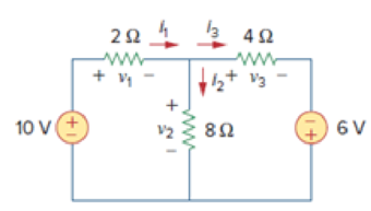
Figure 2.28
For Practice Prob. 2.8.
Expert Solution & Answer
Want to see the full answer?
Check out a sample textbook solution
Students have asked these similar questions
EX Find is, in the circuit below
15ma
2.7
An independent voltage source is characterized by a terminal voltage which
Select one:
a. None of the above
b. is completely independent of the power dissipated by it.
c. is completely independent of the current through it.
d. is completely dependent on the current through it.
An independent voltage source is characterized by a terminal voltage which
Select one:
a. is completely independent of the current through it.
b. None of the above
C. is completely dependent on the current through it.
d. is completely independent of the power dissipated by it.
OO Shot by Hisense H12
Chapter 2 Solutions
Fundamentals of Electric Circuits
Ch. 2.2 - The essential component of a toaster is an...Ch. 2.2 - For the circuit shown in Fig. 2.9, calculate the...Ch. 2.2 - A resistor absorbs an instantaneous power of 30...Ch. 2.3 - How many branches and nodes does the circuit in...Ch. 2.4 - Find v1 and v2 in the circuit of Fig. 2.22. Figure...Ch. 2.4 - Find vx and vo in the circuit of Fig. 2.24. Figure...Ch. 2.4 - Find vo and io in the circuit of Fig. 2.26. Figure...Ch. 2.4 - Find the current and voltages in the circuit shown...Ch. 2.6 - By combining the resistors in Fig.2.36, find Req....Ch. 2.6 - Find Rab for the circuit in Fig.2.39. Figure 2.39...
Ch. 2.6 - Calculate Geq in the circuit of Fig.2.41. Figure...Ch. 2.6 - Find v1 and v2 in the circuit shown in Fig. 2.43....Ch. 2.7 - Transform the wye network in Fig. 2.51 to a delta...Ch. 2.7 - For the bridge network in Fig. 2.54, find Rab and...Ch. 2.8 - Refer to Fig. 2.55 and assume there are six light...Ch. 2.8 - Following the ammeter setup of Fig. 2.61. design...Ch. 2 - The reciprocal of resistance is: (a) voltage (b)...Ch. 2 - Prob. 2RQCh. 2 - Prob. 3RQCh. 2 - The maximum current that a 2W, 80 k resistor can...Ch. 2 - Prob. 5RQCh. 2 - The current I in the circuit of Fig. 2.63 is: (a)...Ch. 2 - The current I0 of Fig. 2.64 is: (a) 4 A (b) 2 A...Ch. 2 - In the circuit in Fig. 2.65, V is: (a) 30 V (b) 14...Ch. 2 - Which of the circuit in Fig. 2.66 will give you...Ch. 2 - In the circuit of Fig. 2.67, a decrease in R3...Ch. 2 - Design a problem, complete with a solution, to...Ch. 2 - Find the hot resistance of a light bulb rated 60...Ch. 2 - A bar of silicon is 4 cm long with a circular...Ch. 2 - (a) Calculate current i in Fig. 2.68 when the...Ch. 2 - For the network graph in Fig. 2.69. find the...Ch. 2 - In the network graph shown in Fig. 2.70, determine...Ch. 2 - Determine the number of branches and nodes in the...Ch. 2 - Design a problem, complete with a solution, to...Ch. 2 - Find i1, i2, and i3 in Fig. 2.73. Figure 2.73 For...Ch. 2 - Determine i1 and i2 in the circuit of Fig. 2.74....Ch. 2 - In the circuit of Fig. 2.75, calculate V1 and V2....Ch. 2 - In the circuit in Fig. 2.76, obtain v1, v2, and...Ch. 2 - For the circuit in Fig. 2.77, use KCL to find the...Ch. 2 - Given the circuit in Fig. 2.78, use KVL to find...Ch. 2 - Calculate v and ix in the circuit of Fig. 2.79....Ch. 2 - Determine Vo in the circuit in Fig. 2.80. Figure...Ch. 2 - Obtain v1 through v3 in the circuit of Fig. 2.81....Ch. 2 - Find I and V in the circuit of Fig. 2.82. Figure...Ch. 2 - From the circuit in Fig. 2.83, find I, the power...Ch. 2 - Determine io in the circuit of Fig. 2.84. Figure...Ch. 2 - Find Vx in the circuit of Fig. 2.85. Figure 2.85...Ch. 2 - Find Vo in the circuit in Fig. 2.86 and the power...Ch. 2 - In the circuit shown in Fig. 2.87, determine Vx...Ch. 2 - For the circuit in Fig. 2.88, find Vo/Vs in terms...Ch. 2 - For the network in Fig. 2.89, find the current,...Ch. 2 - For the circuit in Fig. 2.90, io = 3 A. Calculate...Ch. 2 - Calculate Io in the circuit of Fig. 2.91. Figure...Ch. 2 - Design a problem, using Fig. 2.92, to help other...Ch. 2 - All resistors (R) in Fig. 2.93 are 10 each. Find...Ch. 2 - For the circuit in Fig. 2.95, determine i1 to i5....Ch. 2 - Find i1 through i4 in the circuit in Fig. 2.96....Ch. 2 - Obtain v and i in the circuit of Fig. 2.97. Figure...Ch. 2 - Using series/parallel resistance combination, find...Ch. 2 - Calculate Vo and Io in the circuit of Fig. 2.99....Ch. 2 - Find i and Vo in the circuit of Fig. 2.100. Figure...Ch. 2 - Given the circuit in Fig. 2.101 and that the...Ch. 2 - Find Req and io in the circuit of Fig. 2.102....Ch. 2 - Evaluate Req looking into each set of terminals...Ch. 2 - For the ladder network in Fig. 2.104, find I and...Ch. 2 - If Req = 50 in the circuit of Fig. 2.105, find R....Ch. 2 - Reduce each of the circuits in Fig. 2.106 to a...Ch. 2 - Calculate the equivalent resistance Rab at...Ch. 2 - For the circuits in Fig. 2.108, obtain the...Ch. 2 - Find the equivalent resistance at terminals a-b of...Ch. 2 - Find I in the circuit of Fig. 2.110. Figure 2.110Ch. 2 - Find the equivalent resistance Rab in the circuit...Ch. 2 - Convert the circuits in Fig. 2.112 from Y to ....Ch. 2 - Transform the circuits in Fig. 2.113 from to Y....Ch. 2 - Design a problem to help other students better...Ch. 2 - Obtain the equivalent resistance at the terminals...Ch. 2 - For the circuit shown in Fig. 2.116, find the...Ch. 2 - Obtain the equivalent resistance Rab in each of...Ch. 2 - Consider the circuit in Fig. 2.118. Find the...Ch. 2 - Calculate I0 in the circuit of Fig. 2.119. Figure...Ch. 2 - Determine V in the circuit of Fig. 2.120. Figure...Ch. 2 - Find Req and I in the circuit of Fig. 2.121....Ch. 2 - The 150 W tight bulb in Fig. 2.122 is rated at 110...Ch. 2 - If the three bulbs of Prob. 2.59 are connected in...Ch. 2 - As a design engineer, you are asked to design a...Ch. 2 - Prob. 62PCh. 2 - If an ammeter with an internal resistance of 100 ...Ch. 2 - The potentiometer (adjustable resistor) Rx in Fig....Ch. 2 - Design a circuit that uses a dArsonval meter (with...Ch. 2 - A 20-k/V voltmeter reads 10 V full scale. (a) What...Ch. 2 - (a) Obtain the voltage Vo in the circuit of Fig....Ch. 2 - (a) Find the current I in the circuit of Fig....Ch. 2 - A voltmeter used to measure Vo in the circuit in...Ch. 2 - (a) Consider the Wheatstone bridge shown in Fig....Ch. 2 - Figure 2.131 represents a model of a solar...Ch. 2 - Find Vo in the two-way power divider circuit in...Ch. 2 - An ammeter model consists of an ideal ammeter in...Ch. 2 - The circuit in Fig. 2.134 is to control the speed...Ch. 2 - Find Rab in the four-way power divider circuit in...Ch. 2 - Repeat Prob. 2.75 for the eight-way divider shown...Ch. 2 - Suppose your circuit laboratory has the following...Ch. 2 - In the circuit in Fig. 2.137, the wiper divides...Ch. 2 - Prob. 79CPCh. 2 - A loudspeaker is connected to an amplifier as...Ch. 2 - For a specific application, the circuit shown in...Ch. 2 - The pin diagram of a resistance array is shown in...Ch. 2 - Two delicate devices are rated as shown in Fig....
Knowledge Booster


Learn more about
Need a deep-dive on the concept behind this application? Look no further. Learn more about this topic, electrical-engineering and related others by exploring similar questions and additional content below.Similar questions
- A PV system uses 720 silicon PV cells connected in an array which supplies up to 120 V. .How many PV cells are connected in series if 120 V are needed and one cell delivers 0.5 V? O a. 240 O b. 120 O c. 360 O d. 60arrow_forwardAn independent voltage source is characterized by a terminal voltage which Select one: a. is completely independent of the current through it. on b. is completely independent of the power dissipated by it. c. is completely dependent on the current through it. d. None of the abovearrow_forwardShow all steps and solution. Electrical engineeringarrow_forward
- Refer the circuit shown in Fig. 2.7(a). Draw the graph, one tree and its co-tree. darrow_forwardB) You are required to analyze the operation of DC circuit shown in Fig.2 and apply Ohm's law and Kirchhoff's voltage and current laws to find all the Voltages (with the associated polarities) and currents (with the associated direction)for all resistors. Test your procedures by simulate the circuit using Multisim to verify your hand calculations (Show all steps, equations, and calculations). IR1 R1 IR6 5.1KO IR3 R6 1ko IR2 ww 2.2KO R3 ww R2 1KO V2 V1 10V 5V IR5 IR7 IR4 1KO 2.2KΩ R7 1kQ R4 R5 Figure 2: DC-Circuit ww wwarrow_forwardSelect one: O True O False In a typical electrical circuit, if the resistance of the path in which the current going from node 1 (V.) to node 2 (V,) is 50 then the ampere value of this current will be: O a. V-V2 Ob. V, V, c. V, V, pe here to search Ae TOSHIBAarrow_forward
- A moving-coil instrument gives full-scale deflection with 25 mA. The resistance of the coil is 5 ohm. It is required to convert this meter into an ammeter to read up to 5 A. Find (a) the resistance of the shunt to be connected in parallel with the meter, and (b) the value of series resistance for the above meter to read up to a voltage of 20 V.arrow_forwardLED flashlights use "white" LEDs which have a diode voltage drop of 4.0V. A LED flashlight has the circuit illustrated and will run off several AAA batteries that have a 1.5 VDC rating. a. What is the minimum number of AAA cells needed to turn on the flashlight. b. Would you arrange the batteries in parallel or in series? Vdd R + LED V fritzingarrow_forward1) Draw a circuit below which has resistors both in series and in parallel (each of whose resistances is an integer less than 121 ohms, and different than the others), as well as a DC power source (with an integer potential of less than 121V). 2) Find the equivalent resistance of the resistors (there will be at least 3 of them if they are both in series and parallel), and in a chart figure out the current, voltage, resistance and power through each element. Voltage (V) Current (A) Resistance (Ohms) Power (W)arrow_forward
- What is the function of the circuit? Answer in minimized sum of productsarrow_forwardFundamentals of Electrical Engineering 2020/2021 Dr. Yaseen H. Tahir 19 Example: For the circuit shown in Figure below, find the equivalent resistance and determine all resistor currents and voltages. 50 30 30 2Ω 4Ω Solution:arrow_forwardAn ideal ammeter, which is connected to the output terminals of a circuit, measures a current of 1A. A 1202 resistor is connected to the output terminals to yield a voltage of 30V. Find the Norton equivalent of circuit.arrow_forward
arrow_back_ios
SEE MORE QUESTIONS
arrow_forward_ios
Recommended textbooks for you
 Introductory Circuit Analysis (13th Edition)Electrical EngineeringISBN:9780133923605Author:Robert L. BoylestadPublisher:PEARSON
 Delmar's Standard Textbook Of ElectricityElectrical EngineeringISBN:9781337900348Author:Stephen L. HermanPublisher:Cengage Learning
 Programmable Logic ControllersElectrical EngineeringISBN:9780073373843Author:Frank D. PetruzellaPublisher:McGraw-Hill Education
 Fundamentals of Electric CircuitsElectrical EngineeringISBN:9780078028229Author:Charles K Alexander, Matthew SadikuPublisher:McGraw-Hill Education
 Electric Circuits. (11th Edition)Electrical EngineeringISBN:9780134746968Author:James W. Nilsson, Susan RiedelPublisher:PEARSON
 Engineering ElectromagneticsElectrical EngineeringISBN:9780078028151Author:Hayt, William H. (william Hart), Jr, BUCK, John A.Publisher:Mcgraw-hill Education,
Introductory Circuit Analysis (13th Edition)
Electrical Engineering
ISBN:9780133923605
Author:Robert L. Boylestad
Publisher:PEARSON
Delmar's Standard Textbook Of Electricity
Electrical Engineering
ISBN:9781337900348
Author:Stephen L. Herman
Publisher:Cengage Learning
Programmable Logic Controllers
Electrical Engineering
ISBN:9780073373843
Author:Frank D. Petruzella
Publisher:McGraw-Hill Education
Fundamentals of Electric Circuits
Electrical Engineering
ISBN:9780078028229
Author:Charles K Alexander, Matthew Sadiku
Publisher:McGraw-Hill Education
Electric Circuits. (11th Edition)
Electrical Engineering
ISBN:9780134746968
Author:James W. Nilsson, Susan Riedel
Publisher:PEARSON
Engineering Electromagnetics
Electrical Engineering
ISBN:9780078028151
Author:Hayt, William H. (william Hart), Jr, BUCK, John A.
Publisher:Mcgraw-hill Education,
Superposition Theorem; Author: The Organic Chemistry Tutor;https://www.youtube.com/watch?v=EX52BuZxpQM;License: Standard Youtube License