
Concept explainers
Videos
Obtain the equivalent resistance Rab in each of the circuits of Fig. 2.117. In (b), all resistors have a value of 30 Ω.
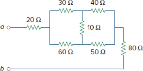
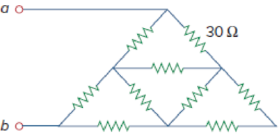
Figure 2.117
(a)
Calculate the equivalent resistor at terminals a-b in Figure 2.117(a).
Answer to Problem 53P
The equivalent resistor at terminals a-b in Figure 2.117(a) is
Explanation of Solution
Formula used:
Consider the delta to wye conversions.
Here,
Consider the expression for
Here,
Consider the expression for
Calculation:
Refer to Figure 2.117(a) in the textbook For Prob.2.53.
Step 1:
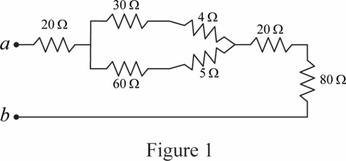
In Figure 2.117(a), convert the delta connection into wye connection.
Consider
Substitute
Substitute
Substitute
Modify Figure 2.117(a) as shown in Figure 1.
Step 2:
In Figure 1, as
Step 3:
In Figure 1, as
Step 4:
In Figure 1, as
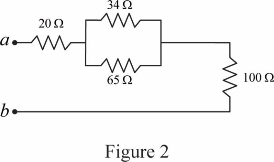
Modify Figure 1 as shown in Figure 2.
Step 5:
In Figure 2, as
Modify Figure 2 as shown in Figure 3.
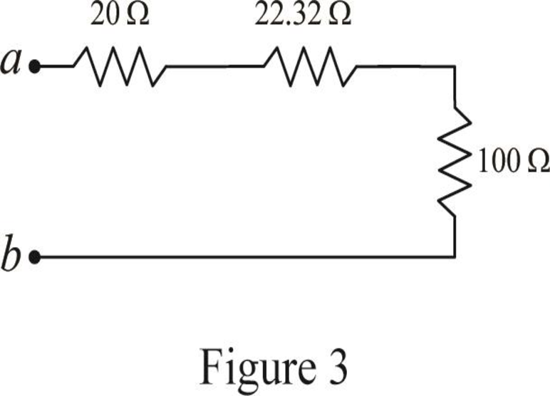
Step 6:
In Figure 3, as
Conclusion:
Thus, the equivalent resistor at terminals a-b in Figure 2.117(a) is
(b)
Calculate the equivalent resistor at terminals a-b in Figure 2.117(b).
Answer to Problem 53P
The equivalent resistor at terminals a-b in Figure 2.117(b) is
Explanation of Solution
Given data:
All resistance have
Formula used:
Consider the following delta to wye conversion, when all branches in a delta consist same value.
Calculation:
Refer to Figure 2.117(b) in the textbook For Prob.2.53.
Step 1:
In Figure 2.117(b), at left most corner of circuit, as two resistors are connected in series, therefore the equivalent resistance for series connected circuit is calculated as follows.
Step 2:
As
Modify Figure 2.117(b) as shown in Figure 4.
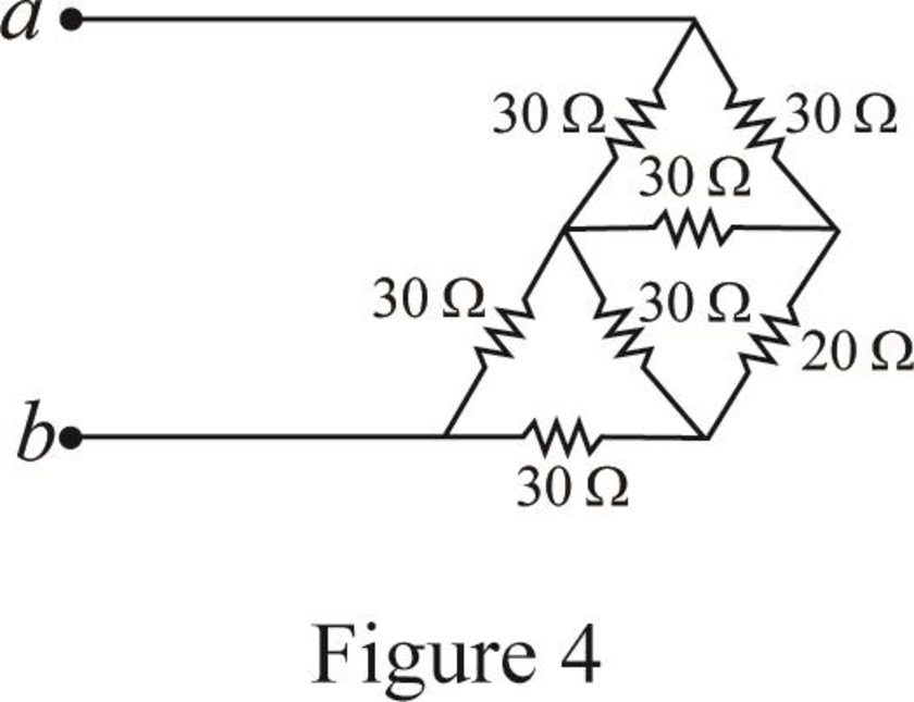
Step 3:
In Figure 4, as in upper part of the circuit all three
Substitute
Since all branch values are same in a delta connection that is
Modify Figure 4 as shown in Figure 5.
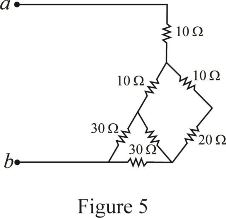
Step 4:
In Figure 5, as
Step 5:
In Figure 5, as in right most part of the circuit all three
Substitute
Since all branch values are same in a delta connection that is
Modify Figure 5 as shown in Figure 6.
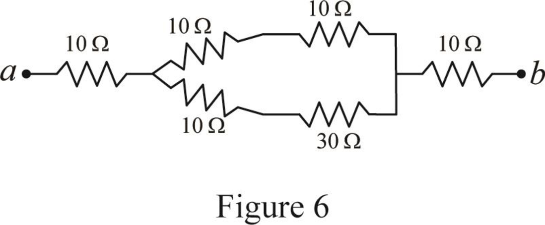
Step 6:
In Figure 6, as
Step 7:
In Figure 6, as
Step 8:
As
Modify Figure 6 as shown in Figure 7.
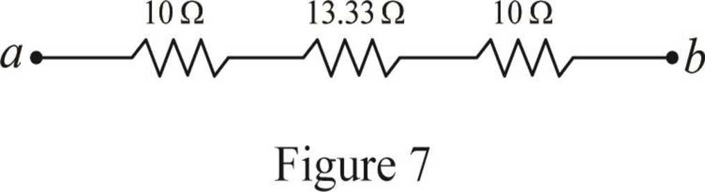
Step 4:
In Figure 7, as
Conclusion:
Thus, the equivalent resistor at terminals a-b in Figure 2.117(b) is
Want to see more full solutions like this?
Chapter 2 Solutions
Fundamentals of Electric Circuits
Additional Engineering Textbook Solutions
Electric Motors and Control Systems
Principles Of Electric Circuits
ANALYSIS+DESIGN OF LINEAR CIRCUITS(LL)
Programmable Logic Controllers
Electric Circuits. (11th Edition)
Principles and Applications of Electrical Engineering


- 4. Find the equivalent Thevenin voltage and equivalent Thevenin resistance respectively as seen from open-circuited terminals A and B to the circuits shown in Fig. 2.173. All resistances are in ohms.arrow_forward9. In the network shown in Fig. 2.177 find the current that would flow if a 2-Ω resistor was connected between points A and B by using.(a) Thevenin’s theorem and (b) Superposition theorem. The two batteries have negligible resistance. [0.82 A]arrow_forwardobserve the image attached of the circuit. calculate the ammount of power that is dissipated through the 3 Ω resisor in the circuit. your answer should have 2 decimal places.arrow_forward
- Determine VL, IL, IZ and IR for the network Figure 2.183 if RL = 180Ω.arrow_forwardA copper conductor wire with a total length of 100ft is used in a 15 amp common household circuit has a resistance of 1.62 ohms/1000ft. If the circuit is fully loaded, approximate the resistance of the conductor? a. 129.6 ohms b. None of these c. 0.130 ohm d. 162 ohms e. 0.162 ohmarrow_forwardDetermine v, for each network of Fig. 2.157 for the input shown. 20 V 2V ldeal Ideal I ka 22 k2 -5 Varrow_forward
- From fig.2, if a supply voltage of 16 V was connected across terminals A and B, computer for the overall power of the circuit.arrow_forwardShow solution. Measure the Norton equivalent resistance by dividing the applied voltage withthe current Ix and Calculate RTH.arrow_forward4. Use source transformation technique to find the current flowing through the 2 Ω resistor in Fig. 2.87 (b). [10 A]arrow_forward
- An ideal voltmeter connected across terminal A and B of Fig.2 in will read – volt. *arrow_forwardFind I and V in the circuit of Fig. 2.82 correctly.arrow_forwardAccording to Sylvania, a light bulb manufacturer, its 75 W CFL floodlightconsumes 23 W and produces 1250 lumens. What is the efficacy of thefloodlight?efficacy = Light Produced (lumens) / Energy Consumed (watts) = 1250/23 = 54arrow_forward
 Introductory Circuit Analysis (13th Edition)Electrical EngineeringISBN:9780133923605Author:Robert L. BoylestadPublisher:PEARSON
 Delmar's Standard Textbook Of ElectricityElectrical EngineeringISBN:9781337900348Author:Stephen L. HermanPublisher:Cengage Learning
 Programmable Logic ControllersElectrical EngineeringISBN:9780073373843Author:Frank D. PetruzellaPublisher:McGraw-Hill Education
 Fundamentals of Electric CircuitsElectrical EngineeringISBN:9780078028229Author:Charles K Alexander, Matthew SadikuPublisher:McGraw-Hill Education
 Electric Circuits. (11th Edition)Electrical EngineeringISBN:9780134746968Author:James W. Nilsson, Susan RiedelPublisher:PEARSON
 Engineering ElectromagneticsElectrical EngineeringISBN:9780078028151Author:Hayt, William H. (william Hart), Jr, BUCK, John A.Publisher:Mcgraw-hill Education,