
Fundamentals of Electric Circuits
6th Edition
ISBN: 9780078028229
Author: Charles K Alexander, Matthew Sadiku
Publisher: McGraw-Hill Education
expand_more
expand_more
format_list_bulleted
Concept explainers
Videos
Textbook Question
Chapter 2, Problem 73P
An ammeter model consists of an ideal ammeter in series with a 20-Ω resistor. It is connected with a current source and an unknown resistor Rx as shown in Fig. 2.133. The ammeter reading is noted. When a potentiometer R is added and adjusted until the ammeter reading drops to one half its previous reading, then R = 65 Ω. What is the value of Rx?
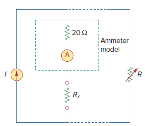
Figure 2.133
Expert Solution & Answer
Want to see the full answer?
Check out a sample textbook solution
Students have asked these similar questions
A circuit has two batteries and four resistors, connected as shown below.
www
592
5 V
392
292
I
192
3 V
1. Find the total effective resistance in the circuit.
2. Write a junction rule for each possible junction in the circuit. Be as specific as you can, but you
don't need to solve for anything.
3. Write a loop rule for each possible loop in the circuit. Be as specific as you can, but you don't
need to solve for anything.
Find the value of a resistor having the following colors, orange, orange, brown, red?
A series-ohmmeter is used to measure the resistance of a given resistor. The ammeter reading is 0.5A, the ammeter resistance is 1.2Ω, the series resistance is 2.4Ω, and the ohmmeter battery is 9V.
Draw the practical circuit for this measurement?
Find the full-scale deflection?
Find the half-deflection resistance of the ohmmeter?
Determine the resistance value?
For the circuit given, the reading on the ammeter is 3.3 A and the value of resistor is 55 ohms, then the value of
battery or input voltage is given by,
R
A
V
O -51.70 V
O 0.06 V
O 58.30 mV
O 181.50 V
Chapter 2 Solutions
Fundamentals of Electric Circuits
Ch. 2.2 - The essential component of a toaster is an...Ch. 2.2 - For the circuit shown in Fig. 2.9, calculate the...Ch. 2.2 - A resistor absorbs an instantaneous power of 30...Ch. 2.3 - How many branches and nodes does the circuit in...Ch. 2.4 - Find v1 and v2 in the circuit of Fig. 2.22. Figure...Ch. 2.4 - Find vx and vo in the circuit of Fig. 2.24. Figure...Ch. 2.4 - Find vo and io in the circuit of Fig. 2.26. Figure...Ch. 2.4 - Find the current and voltages in the circuit shown...Ch. 2.6 - By combining the resistors in Fig.2.36, find Req....Ch. 2.6 - Find Rab for the circuit in Fig.2.39. Figure 2.39...
Ch. 2.6 - Calculate Geq in the circuit of Fig.2.41. Figure...Ch. 2.6 - Find v1 and v2 in the circuit shown in Fig. 2.43....Ch. 2.7 - Transform the wye network in Fig. 2.51 to a delta...Ch. 2.7 - For the bridge network in Fig. 2.54, find Rab and...Ch. 2.8 - Refer to Fig. 2.55 and assume there are six light...Ch. 2.8 - Following the ammeter setup of Fig. 2.61. design...Ch. 2 - The reciprocal of resistance is: (a) voltage (b)...Ch. 2 - Prob. 2RQCh. 2 - Prob. 3RQCh. 2 - The maximum current that a 2W, 80 k resistor can...Ch. 2 - Prob. 5RQCh. 2 - The current I in the circuit of Fig. 2.63 is: (a)...Ch. 2 - The current I0 of Fig. 2.64 is: (a) 4 A (b) 2 A...Ch. 2 - In the circuit in Fig. 2.65, V is: (a) 30 V (b) 14...Ch. 2 - Which of the circuit in Fig. 2.66 will give you...Ch. 2 - In the circuit of Fig. 2.67, a decrease in R3...Ch. 2 - Design a problem, complete with a solution, to...Ch. 2 - Find the hot resistance of a light bulb rated 60...Ch. 2 - A bar of silicon is 4 cm long with a circular...Ch. 2 - (a) Calculate current i in Fig. 2.68 when the...Ch. 2 - For the network graph in Fig. 2.69. find the...Ch. 2 - In the network graph shown in Fig. 2.70, determine...Ch. 2 - Determine the number of branches and nodes in the...Ch. 2 - Design a problem, complete with a solution, to...Ch. 2 - Find i1, i2, and i3 in Fig. 2.73. Figure 2.73 For...Ch. 2 - Determine i1 and i2 in the circuit of Fig. 2.74....Ch. 2 - In the circuit of Fig. 2.75, calculate V1 and V2....Ch. 2 - In the circuit in Fig. 2.76, obtain v1, v2, and...Ch. 2 - For the circuit in Fig. 2.77, use KCL to find the...Ch. 2 - Given the circuit in Fig. 2.78, use KVL to find...Ch. 2 - Calculate v and ix in the circuit of Fig. 2.79....Ch. 2 - Determine Vo in the circuit in Fig. 2.80. Figure...Ch. 2 - Obtain v1 through v3 in the circuit of Fig. 2.81....Ch. 2 - Find I and V in the circuit of Fig. 2.82. Figure...Ch. 2 - From the circuit in Fig. 2.83, find I, the power...Ch. 2 - Determine io in the circuit of Fig. 2.84. Figure...Ch. 2 - Find Vx in the circuit of Fig. 2.85. Figure 2.85...Ch. 2 - Find Vo in the circuit in Fig. 2.86 and the power...Ch. 2 - In the circuit shown in Fig. 2.87, determine Vx...Ch. 2 - For the circuit in Fig. 2.88, find Vo/Vs in terms...Ch. 2 - For the network in Fig. 2.89, find the current,...Ch. 2 - For the circuit in Fig. 2.90, io = 3 A. Calculate...Ch. 2 - Calculate Io in the circuit of Fig. 2.91. Figure...Ch. 2 - Design a problem, using Fig. 2.92, to help other...Ch. 2 - All resistors (R) in Fig. 2.93 are 10 each. Find...Ch. 2 - For the circuit in Fig. 2.95, determine i1 to i5....Ch. 2 - Find i1 through i4 in the circuit in Fig. 2.96....Ch. 2 - Obtain v and i in the circuit of Fig. 2.97. Figure...Ch. 2 - Using series/parallel resistance combination, find...Ch. 2 - Calculate Vo and Io in the circuit of Fig. 2.99....Ch. 2 - Find i and Vo in the circuit of Fig. 2.100. Figure...Ch. 2 - Given the circuit in Fig. 2.101 and that the...Ch. 2 - Find Req and io in the circuit of Fig. 2.102....Ch. 2 - Evaluate Req looking into each set of terminals...Ch. 2 - For the ladder network in Fig. 2.104, find I and...Ch. 2 - If Req = 50 in the circuit of Fig. 2.105, find R....Ch. 2 - Reduce each of the circuits in Fig. 2.106 to a...Ch. 2 - Calculate the equivalent resistance Rab at...Ch. 2 - For the circuits in Fig. 2.108, obtain the...Ch. 2 - Find the equivalent resistance at terminals a-b of...Ch. 2 - Find I in the circuit of Fig. 2.110. Figure 2.110Ch. 2 - Find the equivalent resistance Rab in the circuit...Ch. 2 - Convert the circuits in Fig. 2.112 from Y to ....Ch. 2 - Transform the circuits in Fig. 2.113 from to Y....Ch. 2 - Design a problem to help other students better...Ch. 2 - Obtain the equivalent resistance at the terminals...Ch. 2 - For the circuit shown in Fig. 2.116, find the...Ch. 2 - Obtain the equivalent resistance Rab in each of...Ch. 2 - Consider the circuit in Fig. 2.118. Find the...Ch. 2 - Calculate I0 in the circuit of Fig. 2.119. Figure...Ch. 2 - Determine V in the circuit of Fig. 2.120. Figure...Ch. 2 - Find Req and I in the circuit of Fig. 2.121....Ch. 2 - The 150 W tight bulb in Fig. 2.122 is rated at 110...Ch. 2 - If the three bulbs of Prob. 2.59 are connected in...Ch. 2 - As a design engineer, you are asked to design a...Ch. 2 - Prob. 62PCh. 2 - If an ammeter with an internal resistance of 100 ...Ch. 2 - The potentiometer (adjustable resistor) Rx in Fig....Ch. 2 - Design a circuit that uses a dArsonval meter (with...Ch. 2 - A 20-k/V voltmeter reads 10 V full scale. (a) What...Ch. 2 - (a) Obtain the voltage Vo in the circuit of Fig....Ch. 2 - (a) Find the current I in the circuit of Fig....Ch. 2 - A voltmeter used to measure Vo in the circuit in...Ch. 2 - (a) Consider the Wheatstone bridge shown in Fig....Ch. 2 - Figure 2.131 represents a model of a solar...Ch. 2 - Find Vo in the two-way power divider circuit in...Ch. 2 - An ammeter model consists of an ideal ammeter in...Ch. 2 - The circuit in Fig. 2.134 is to control the speed...Ch. 2 - Find Rab in the four-way power divider circuit in...Ch. 2 - Repeat Prob. 2.75 for the eight-way divider shown...Ch. 2 - Suppose your circuit laboratory has the following...Ch. 2 - In the circuit in Fig. 2.137, the wiper divides...Ch. 2 - Prob. 79CPCh. 2 - A loudspeaker is connected to an amplifier as...Ch. 2 - For a specific application, the circuit shown in...Ch. 2 - The pin diagram of a resistance array is shown in...Ch. 2 - Two delicate devices are rated as shown in Fig....
Knowledge Booster


Learn more about
Need a deep-dive on the concept behind this application? Look no further. Learn more about this topic, electrical-engineering and related others by exploring similar questions and additional content below.Similar questions
- Determine the total resistance, Rī, and current, I, for the circuit in Figure Q1(b). 30V- RT 50Ω 2002 4092 7092 m Figure Q1(b) 3002 m 6092 [Answer: 22.430, 1.34A]arrow_forward10. A loaded zener regulator is shown in Figure 3-70. Vz = 5.1 V at Iz = 49 mA, IZK = 1 mA, Zz = 70, and IzM = 70 mA. Determine the minimum and maximum permissible load currents. > FIGURE 3-70 R Multisim file circuits are identified + 22 Ω with a logo and are in the Problems folder on the companion website. Filenames correspond to figure numbers (e.g., F03-70). VIN 8 V IN4733Aarrow_forwardWhich of the following statement is not correct? voltage source is an active element current source is a passive element resistance is a passive element conductance is a passive elementarrow_forward
- a) For the network shown in the below figure, the value of current needs to be measured in the 10002 by connecting a 202 ammeter between two terminals A and B, find the following: 1) The actual value of current. 2) The measured value of curent. 3) The percentage error in measurement. 4) The accuracy of measurement. XMM1 R1 R3 2000Q 10000 R2 V1 20V 20000 Barrow_forwardCalculate (a) the current drawn from the source, (b) the p.d. across each resistor, (c) the current through each resistor, and (d) the power dissipated by the 5-ohm resistor A I 1₁ R₁ 12 492 R₂ 692 VAB R3 B 502 VBC E 18 V LR₁4 392 15 R 692 16 Re 892 VCD Darrow_forwardDetermine the equivalent resistance between terminals a and b. R1 R2 1 Ohm 2 Ohms R3 3 Ohms R4 R5 -b 4 Ohms 5 Ohms O 7.6547 0 6.7520 Q O 5.9253 0 6.9130 0arrow_forward
- If three resistance in parallel, R1=3 ohm. , R2=50 mohm, R3= 1 kohm. the total R is: 1038 ohm 0.04917 ohm O 0.534 ohm O 1.87 ohmarrow_forwarda 4 k ohms resistor with a tolerance of + or -2% carries a current of 2 A. The current was measured by an analog ammeter with a range of 0 to 4 A with a quoted inaccuracy of + or -6% of the full scale. The likely maximum error in calculating the power dissipated in the resistor is: ** I need a step by step answer please**arrow_forwardDo your resistors follow Ohm’s law? Base your answer on your experimental data.arrow_forward
- Q1. a) For the circuit shown in figure 1, determine the following: i) The total resistance ii) The voltage across R3 iii) The current through R4 iv) Using any simulation tools, verify your answer in parts (ii & iii) 70 ohms R₂ 15 v til+ R1 6052 Figure 1 R3 8092 R4 60 ohmsarrow_forwardDetermine the equivalent resistance between terminals a and b. R1 R2 ww 1 Ohm -a 2 Ohms R3. 3 Ohms R4 R5 4 Ohms 5 Ohms 6.7520 Q 6.9130 Q 7.6547 Q 5.9253 Qarrow_forwardTwo resistors R1 (100KΩ) and R2 (50 KΩ) are connected in series with a 150 Volt voltage source, if you want to measure the voltage at R2 with voltmeter 1 (sensitivity = 1KΩ/V) and voltmeter 2 (sensitivity = 20KΩ/V). Determine (a) the readings per voltmeter, (b) the percentage error of each reading. (make a picture of the circuit first).arrow_forward
arrow_back_ios
SEE MORE QUESTIONS
arrow_forward_ios
Recommended textbooks for you
 Introductory Circuit Analysis (13th Edition)Electrical EngineeringISBN:9780133923605Author:Robert L. BoylestadPublisher:PEARSON
 Delmar's Standard Textbook Of ElectricityElectrical EngineeringISBN:9781337900348Author:Stephen L. HermanPublisher:Cengage Learning
 Programmable Logic ControllersElectrical EngineeringISBN:9780073373843Author:Frank D. PetruzellaPublisher:McGraw-Hill Education
 Fundamentals of Electric CircuitsElectrical EngineeringISBN:9780078028229Author:Charles K Alexander, Matthew SadikuPublisher:McGraw-Hill Education
 Electric Circuits. (11th Edition)Electrical EngineeringISBN:9780134746968Author:James W. Nilsson, Susan RiedelPublisher:PEARSON
 Engineering ElectromagneticsElectrical EngineeringISBN:9780078028151Author:Hayt, William H. (william Hart), Jr, BUCK, John A.Publisher:Mcgraw-hill Education,
Introductory Circuit Analysis (13th Edition)
Electrical Engineering
ISBN:9780133923605
Author:Robert L. Boylestad
Publisher:PEARSON
Delmar's Standard Textbook Of Electricity
Electrical Engineering
ISBN:9781337900348
Author:Stephen L. Herman
Publisher:Cengage Learning
Programmable Logic Controllers
Electrical Engineering
ISBN:9780073373843
Author:Frank D. Petruzella
Publisher:McGraw-Hill Education
Fundamentals of Electric Circuits
Electrical Engineering
ISBN:9780078028229
Author:Charles K Alexander, Matthew Sadiku
Publisher:McGraw-Hill Education
Electric Circuits. (11th Edition)
Electrical Engineering
ISBN:9780134746968
Author:James W. Nilsson, Susan Riedel
Publisher:PEARSON
Engineering Electromagnetics
Electrical Engineering
ISBN:9780078028151
Author:Hayt, William H. (william Hart), Jr, BUCK, John A.
Publisher:Mcgraw-hill Education,
Superposition Theorem; Author: The Organic Chemistry Tutor;https://www.youtube.com/watch?v=EX52BuZxpQM;License: Standard Youtube License