
Introductory Circuit Analysis (13th Edition)
13th Edition
ISBN: 9780133923605
Author: Robert L. Boylestad
Publisher: PEARSON
expand_more
expand_more
format_list_bulleted
Concept explainers
Videos
Textbook Question
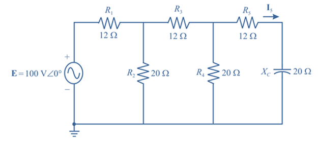
Chapter 17, Problem 14P
Find the current I5 for the network in Fig. 17.51. Note the effect of one reactive element on the resulting calculations.
Expert Solution & Answer
Want to see the full answer?
Check out a sample textbook solution
Students have asked these similar questions
Q): For the figure shown below, use nodal analysis to find the value of Vo
2Vx
2/k A
Ika
Ika
4v
2/kA
characteristic
Keoping
of
pa ra mete os constant, plot to/Vos
for L= LI and
all
other
MOSEET
Given a series circuit comprised of the following element: 99.17-ohm resistor, practical inductor with internal resistance of 0.43 ohm and reactance of 69.71 ohms; and a capacitor with reactance of 11.6 ohms. Compute for the magnitude of its equivalent impedance in ohms.
Compute to the nearest 4 decimal places. No Scientific notation. Do not round off in the middle of calculation. Use stored values.
Chapter 17 Solutions
Introductory Circuit Analysis (13th Edition)
Ch. 17 - For theseries-parallel network in Fig.17.38. a....Ch. 17 - For the network in Fig. 17.39: a. Find the total...Ch. 17 - For the network in FIg. 17.40: a. Find the total...Ch. 17 - For the network in Fig. 17.41: a. Find the total...Ch. 17 - For the network in Fig. 17.42: a. Find the current...Ch. 17 - For the network in Fig. 17.43: a. Find the current...Ch. 17 - For the network in Fig. 17.44: a. Find the current...Ch. 17 - For the network in Fig. 17.45: a. Find the source...Ch. 17 - For the network of Fig. 17.46: a. Find the voltage...Ch. 17 - For the network in Fig. 17.47: a. Find the total...
Ch. 17 - For the network in Fig. 17.48: a. Find the total...Ch. 17 - For the network of Fig. 17.49: a. Find the total...Ch. 17 - For the network of Fig. 17.50: a. Find the total...Ch. 17 - Find the current I5 for the network in Fig. 17.51....Ch. 17 - Find the average power delivered to R5 in Fig....Ch. 17 - For the ladder network of Fig. 17.53: a. Find the...Ch. 17 - Prob. 17PCh. 17 - PSpice or Multisim For Problems 15 through 18, use...Ch. 17 - PSpice or Multisim For Problems 15 through 18, use...Ch. 17 - PSpice or Multisim For Problems 15 through 18, use...Ch. 17 - PSpice or Multisim For Problems 15 through 18, use...
Knowledge Booster


Learn more about
Need a deep-dive on the concept behind this application? Look no further. Learn more about this topic, electrical-engineering and related others by exploring similar questions and additional content below.Similar questions
- A half-wave thyristor converter supplies a purely inductive load, as shown in Fig. If the triggering angle of the thyristor is 120°, the extinction angle will be XX Vmsinot LEarrow_forwardThe input impedance of an ac network can be measured with an ohmmeter. a.False b.True c.True if the ohmmeter is digital d.Sometimesarrow_forward2. Form the Y bus of the following data Given table Bus From To 1 2 3 1123 4 4 4 Resistance in Reactance in PU PU 0.05 0.15 0.10 0.30 0.20 0.40 0.10 0.30 0.05 0.15arrow_forward
- Given a series circuit comprised of the following element: 81.59-ohm resistor, practical inductor with internal resistance of 0.99 ohm and reactance of 54.29 ohms; and a capacitor with reactance of 6.15 ohms. Compute for equivalent impedance angle in degrees. Note: Follow this reminder carefully. Compute to the nearest 4 decimal places. No Scientific notation. Do not round off in the middle of calculation. Use stored values. Write the numerical values only. No units in your final answer. Spaces are not allowed. Excessive number of decimals as compared to the required number of decimals may result to an incorrect answer.arrow_forwardBriefly explain about a) Primary transmission b) Secondary transmission c) Primary distribution d) Secondary distributionarrow_forward2.1 An ESKOM engineer made the following recommendation for 220 V, 50Hz line. 150µF capacitor and a 75 mH inductor for the TCR to correct the power factor to be at unity. What is the delay angle when the load current has a reactive component of -j9 A?arrow_forward
- كلية العراق الجامعة LTE .l Ims.iuc.edu.iq 06) V. =....v (A) 14 ЗА (B)12 6v V. 34n (c)10 (D)=20 Q7) R3 : ... RI R2 504 AMMA (A) 40 ŹR3 (B)50 Sjoon 100n (c) 100 (D) 80 Ds) By nodal analysis , Vo- ..-- v (A) - I (8) - 2 (c) I (D) 2 Da) By source conversion, 10 5 VE :2V Io = ..... 2A 4V (A) 2 (B) I (c) 4A (D) 3 A By superposition, Vab= -- V 30n 30n3 b1 (A) 40 (B)50 (e)60 (0)70 2A >arrow_forwardPleasearrow_forwardD13/find Uc ik we reverse the orientation af the diode in fig. +lovarrow_forward
- 1. The secondary of a three-phase transformer is shown in Fig. (1). The RMS secondary phase voltage is 45V. i. Draw the waveforms of load voltage, 中 phase A diode (D1) current, and diode (D1) voltage. Calculate the average output voltage. Calculate the value of R if the load power phae ii. ii. ண+ is 100w. phase iv. Determine the diode ratings. (S = start F= finish) Vo Fig. (1)arrow_forwardvodafone TR 3 AE l 63 I+ 15:53 G ceviri d)birçok deliğe A kitchen zero temperature undoped semiconductor has: Please choose one: a) many free electrons b) several free electrodes c) no holes or free electrons d) many holes Geri bildirim 米 ... Discover Anlık görü... Ara Koleksiyo. Diğer 习arrow_forwardpro blem: Sal ve the Following eircuit the wmesh and nod analysis. by using method. Formulate the eguations into a matrin with of Variables.. n minimum number 42 22 2.arrow_forward
arrow_back_ios
SEE MORE QUESTIONS
arrow_forward_ios
Recommended textbooks for you
 Introductory Circuit Analysis (13th Edition)Electrical EngineeringISBN:9780133923605Author:Robert L. BoylestadPublisher:PEARSON
 Delmar's Standard Textbook Of ElectricityElectrical EngineeringISBN:9781337900348Author:Stephen L. HermanPublisher:Cengage Learning
 Programmable Logic ControllersElectrical EngineeringISBN:9780073373843Author:Frank D. PetruzellaPublisher:McGraw-Hill Education
 Fundamentals of Electric CircuitsElectrical EngineeringISBN:9780078028229Author:Charles K Alexander, Matthew SadikuPublisher:McGraw-Hill Education
 Electric Circuits. (11th Edition)Electrical EngineeringISBN:9780134746968Author:James W. Nilsson, Susan RiedelPublisher:PEARSON
 Engineering ElectromagneticsElectrical EngineeringISBN:9780078028151Author:Hayt, William H. (william Hart), Jr, BUCK, John A.Publisher:Mcgraw-hill Education,
Introductory Circuit Analysis (13th Edition)
Electrical Engineering
ISBN:9780133923605
Author:Robert L. Boylestad
Publisher:PEARSON
Delmar's Standard Textbook Of Electricity
Electrical Engineering
ISBN:9781337900348
Author:Stephen L. Herman
Publisher:Cengage Learning
Programmable Logic Controllers
Electrical Engineering
ISBN:9780073373843
Author:Frank D. Petruzella
Publisher:McGraw-Hill Education
Fundamentals of Electric Circuits
Electrical Engineering
ISBN:9780078028229
Author:Charles K Alexander, Matthew Sadiku
Publisher:McGraw-Hill Education
Electric Circuits. (11th Edition)
Electrical Engineering
ISBN:9780134746968
Author:James W. Nilsson, Susan Riedel
Publisher:PEARSON
Engineering Electromagnetics
Electrical Engineering
ISBN:9780078028151
Author:Hayt, William H. (william Hart), Jr, BUCK, John A.
Publisher:Mcgraw-hill Education,
Understanding Amplitude Modulation; Author: Rohde Schwarz;https://www.youtube.com/watch?v=I46eP8uZh_Y;License: Standard Youtube License