
Introductory Circuit Analysis (13th Edition)
13th Edition
ISBN: 9780133923605
Author: Robert L. Boylestad
Publisher: PEARSON
expand_more
expand_more
format_list_bulleted
Concept explainers
Videos
Textbook Question
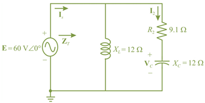
Chapter 17, Problem 3P
For the network in FIg. 17.40:
a. Find the total impedance ZT.
b. Find the current IS.
c. Calculate I2 using the current divider rule.
d. Calculate VC using the voltage divider rule.
e. Calculate the average power delivered to the network.
Expert Solution & Answer
Want to see the full answer?
Check out a sample textbook solution
Students have asked these similar questions
Which among the following component will not be affected, if outage magnitude increases?
a. Remaining generation capacity
b. Expected Energy not served
C Available generation capacity
d. Energy Demand
In a power system, which one of the following is not a state variable:
Select one:
O a. None of these
O b. Voltage magnitude
O c. Line impedance
O d. Relative phase angle at the system nodes
1- Determine YT and ZT
2- Sketch the admittance diagram.
3- Find E and IL.
4- Compute the power factor of the network and the power
delivered to the network
5- Determine the equivalent series circuit as far as the terminal
charac-teristics of the network are concerned.
6- Using the equivalent circuit developed in part e, calculate E,
and compare it with the result of part c.
7- Determine the power delivered to the network, and
compare it with the solution of part (d).
8- Determine the equivalent parallel network from the
equivalent series circuit, and calculate the total admittance
Yr. Compare the result with the solution of part (a).
i= √2 (12) sin 1000r
ZT
R₁100 R₂40 L₁6 mH L12 mH
80 μF
20 µF
Chapter 17 Solutions
Introductory Circuit Analysis (13th Edition)
Ch. 17 - For theseries-parallel network in Fig.17.38. a....Ch. 17 - For the network in Fig. 17.39: a. Find the total...Ch. 17 - For the network in FIg. 17.40: a. Find the total...Ch. 17 - For the network in Fig. 17.41: a. Find the total...Ch. 17 - For the network in Fig. 17.42: a. Find the current...Ch. 17 - For the network in Fig. 17.43: a. Find the current...Ch. 17 - For the network in Fig. 17.44: a. Find the current...Ch. 17 - For the network in Fig. 17.45: a. Find the source...Ch. 17 - For the network of Fig. 17.46: a. Find the voltage...Ch. 17 - For the network in Fig. 17.47: a. Find the total...
Ch. 17 - For the network in Fig. 17.48: a. Find the total...Ch. 17 - For the network of Fig. 17.49: a. Find the total...Ch. 17 - For the network of Fig. 17.50: a. Find the total...Ch. 17 - Find the current I5 for the network in Fig. 17.51....Ch. 17 - Find the average power delivered to R5 in Fig....Ch. 17 - For the ladder network of Fig. 17.53: a. Find the...Ch. 17 - Prob. 17PCh. 17 - PSpice or Multisim For Problems 15 through 18, use...Ch. 17 - PSpice or Multisim For Problems 15 through 18, use...Ch. 17 - PSpice or Multisim For Problems 15 through 18, use...Ch. 17 - PSpice or Multisim For Problems 15 through 18, use...
Additional Engineering Textbook Solutions
Find more solutions based on key concepts
Explain the main function of each of the following major components of a PLC: a. Processor module (CPU) b. I/O ...
Programmable Logic Controllers
When travelers from the USA and Canada visit Europe, they encounter a different power distribution system. Wall...
Electric machinery fundamentals
With respect to the circuit in Fig. 5.90, (a) employ Thévenin’s theorem to determine the equivalent network see...
Loose Leaf for Engineering Circuit Analysis Format: Loose-leaf
For the “tank” circuit in Fig. 14.79, find the resonant frequency.
Figure 14.79
For Probs. 14.39, 14.71, and 1...
Fundamentals of Electric Circuits
Electric power systems provide energy in a variety of commercial and industrial settings. Make a list of system...
Principles and Applications of Electrical Engineering
Design an ideal inverting op-amp circuit such that the voltage gain is Av=25 . The maximum current in any resis...
Microelectronics: Circuit Analysis and Design
Knowledge Booster


Learn more about
Need a deep-dive on the concept behind this application? Look no further. Learn more about this topic, electrical-engineering and related others by exploring similar questions and additional content below.Similar questions
- For a given power transfer which of the following is true. O Delta is associated with larger line voltage O Delta is associated with larger line current O Star is associated with larger line current O Conductors in delta system have smaller cross sectional area A Transformer having 1400 Primary turns connected to a 252 V a.c. supply. For a secondary Voltage of 416 V, the number of Secondary Turns should be No. of Turns in the Secondary hp fs 19 11 44 f10 & 7 8 V 60arrow_forwardUse the image to answer the 3 part question. A)determine the impedance of the circuit. B)determine the average power provided by the source to the circuit. C) Determine Vr the maximum voltage drop through the resistor and Vc max the maximum voltage drop through the capacitorarrow_forwardWhen the waveform shown in fig. (1) is applied to true responding ac voltmeter, the output would be (5.314 V). If the same signal is applied to average responding ac voltmeter, what will be: 1. The indicate value. 2. The true value. 3. The true form factor. 4. The indicate crest factor.arrow_forward
- What is the maximum power that can be transferred to the marked variable (in watts)? Ans. cannot be in terms of V, or Iş 12N Is -> Vs RL ЗА SW1arrow_forward25) Which one of the following is true of ac circuits with reactive elements? 25) A) The magnitude of the voltage across any one element can never exceed the applied voltage. B) The smaller the resistive element of a circuit, the closer the power factor is to unity. C) Depending on the frequency applied, the circuit can look either inductive or capacitive. D) The impedance of any one element can never exceed the total network impedance.arrow_forwarddetermine the network below. sketch the power trianglearrow_forward
- ID Тopic Draw the circuit diagram of Two quadrant chopper which is having average load current might be positive or negative. Explain each quadrant operation with neat sketch. Group 6: S.No 2arrow_forwardFor a system with total complex power of 10000 + 7500j VA, nominal voltage of 250 angle 30 deg. and 50HZ system frequency. Vrms. When this system power factor is raised to power factor 0.9 leading. Determine the new current. 44.44 angle 55.84 deg. A 44.44 angle -55.84 deg. A 50 angle -66.87 deg. A 50 angle 66.87 deg. Aarrow_forwardQ1: A 50HZ,11KV,3-ph,alternator with earthed neutral has a reactance of 50\ph and is connected to bus bar through a C.B.The distributed capacitance up to C.B between phase and neutral is 0.01HF,Determine: 1-The restriking voltage across the contacts of the breaker, 2-The frequency of oscillation,and 3-The voltage across the capacitance. (if the disconnecting capacitive tank)? Q2:Repeat (1,2,and 3) in Q1 if the P.F. of the fault was capacitance current breaking due to 0.4? Q3:Repeat (1,2,and 3) in Q1 if the current chops at an instantaneous rate of 8A?arrow_forward
- ?? The step down chopper is operating at 1 kHz. Other data are V = 240 V, L = 10 mH, R = 10 and duty cycle 60%. (a) current. Determine the DC component of the load current and the peak-to-peak ripple in the load (b) By how much will the above values change if the frequency is increased to 2 kHz other data remaining the same. (c) What will the change in the values determined in (a) if the frequency is unchanged but the inductance value is increased to 20 mH, other data remaining the same.arrow_forwardH.W.pdf Dr. Kanaan A. Jalal University of Technology/ Dept. of Electrical Eng. H.W Q.) For the circuit shown, using Superposition Theorem: 1) Calculate the current through 4 resistor. 2) Find the voltage across 42. 10A 30 10V S40 1arrow_forwardThe following table gives the parameters for a distribution system. This system a) Draw the frequency domain equivalent circuit b) Find the voltage across the load impedance c) Find the average, reactive and complex power of the system d) Calculate the power factor of the source e) What percentage of the average power is dissipated over the line and source impedances find it f) To make the power factor 1, find the value of the circuit element to be connected parallel to the load Parameter Source (rms) Frequency Source Phase Angle source internal impedance Line Impedance Line Length Load Impedance findfind itValue 12kV 60Hz 0 0,5+j0,5 Ω 0,02+j0,03 02/km 200km 55,5+j75,5 Ω Not. Solve this question in detail step by step and explain your requests in detailarrow_forward
arrow_back_ios
SEE MORE QUESTIONS
arrow_forward_ios
Recommended textbooks for you
 Introductory Circuit Analysis (13th Edition)Electrical EngineeringISBN:9780133923605Author:Robert L. BoylestadPublisher:PEARSON
 Delmar's Standard Textbook Of ElectricityElectrical EngineeringISBN:9781337900348Author:Stephen L. HermanPublisher:Cengage Learning
 Programmable Logic ControllersElectrical EngineeringISBN:9780073373843Author:Frank D. PetruzellaPublisher:McGraw-Hill Education
 Fundamentals of Electric CircuitsElectrical EngineeringISBN:9780078028229Author:Charles K Alexander, Matthew SadikuPublisher:McGraw-Hill Education
 Electric Circuits. (11th Edition)Electrical EngineeringISBN:9780134746968Author:James W. Nilsson, Susan RiedelPublisher:PEARSON
 Engineering ElectromagneticsElectrical EngineeringISBN:9780078028151Author:Hayt, William H. (william Hart), Jr, BUCK, John A.Publisher:Mcgraw-hill Education,
Introductory Circuit Analysis (13th Edition)
Electrical Engineering
ISBN:9780133923605
Author:Robert L. Boylestad
Publisher:PEARSON
Delmar's Standard Textbook Of Electricity
Electrical Engineering
ISBN:9781337900348
Author:Stephen L. Herman
Publisher:Cengage Learning
Programmable Logic Controllers
Electrical Engineering
ISBN:9780073373843
Author:Frank D. Petruzella
Publisher:McGraw-Hill Education
Fundamentals of Electric Circuits
Electrical Engineering
ISBN:9780078028229
Author:Charles K Alexander, Matthew Sadiku
Publisher:McGraw-Hill Education
Electric Circuits. (11th Edition)
Electrical Engineering
ISBN:9780134746968
Author:James W. Nilsson, Susan Riedel
Publisher:PEARSON
Engineering Electromagnetics
Electrical Engineering
ISBN:9780078028151
Author:Hayt, William H. (william Hart), Jr, BUCK, John A.
Publisher:Mcgraw-hill Education,
Nodal Analysis for Circuits Explained; Author: Engineer4Free;https://www.youtube.com/watch?v=f-sbANgw4fo;License: Standard Youtube License