
Introductory Circuit Analysis (13th Edition)
13th Edition
ISBN: 9780133923605
Author: Robert L. Boylestad
Publisher: PEARSON
expand_more
expand_more
format_list_bulleted
Concept explainers
Videos
Textbook Question
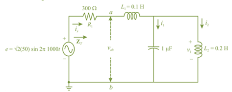
Chapter 17, Problem 11P
For the network in Fig. 17.48:
a. Find the total impedance ZT.
b. Find the source current lS in phasor form.
c. Find the currents I1 and 12 in phasor tocm.
d. Find the voltages V1 and Vab in phasor form.
e. Find the average power delivered to the network.
f. Find the power factor of the network, and indicate whether it is leading or lagging.
Expert Solution & Answer
Want to see the full answer?
Check out a sample textbook solution
Students have asked these similar questions
a.) Solve for the current flowing through the load (magnitude).
b.) What is the phase angle of the current flowing through the load?
c.) Solve for the voltage across the load.
For the given circuit below
a. Calculate E, IR, and IL, in phasor form.b. Calculate the total power factor (leading or lagging) and the average power delivered to the circuit.c. Draw the admittance diagram and draw the phasor diagram of the currents Is, IR, and IL, and the voltage E.
Use the image to answer the 3 part question.
A)determine the impedance of the circuit.
B)determine the average power provided by the source to the circuit.
C) Determine Vr the maximum voltage drop through the resistor and Vc max the maximum voltage drop through the capacitor
Chapter 17 Solutions
Introductory Circuit Analysis (13th Edition)
Ch. 17 - For theseries-parallel network in Fig.17.38. a....Ch. 17 - For the network in Fig. 17.39: a. Find the total...Ch. 17 - For the network in FIg. 17.40: a. Find the total...Ch. 17 - For the network in Fig. 17.41: a. Find the total...Ch. 17 - For the network in Fig. 17.42: a. Find the current...Ch. 17 - For the network in Fig. 17.43: a. Find the current...Ch. 17 - For the network in Fig. 17.44: a. Find the current...Ch. 17 - For the network in Fig. 17.45: a. Find the source...Ch. 17 - For the network of Fig. 17.46: a. Find the voltage...Ch. 17 - For the network in Fig. 17.47: a. Find the total...
Ch. 17 - For the network in Fig. 17.48: a. Find the total...Ch. 17 - For the network of Fig. 17.49: a. Find the total...Ch. 17 - For the network of Fig. 17.50: a. Find the total...Ch. 17 - Find the current I5 for the network in Fig. 17.51....Ch. 17 - Find the average power delivered to R5 in Fig....Ch. 17 - For the ladder network of Fig. 17.53: a. Find the...Ch. 17 - Prob. 17PCh. 17 - PSpice or Multisim For Problems 15 through 18, use...Ch. 17 - PSpice or Multisim For Problems 15 through 18, use...Ch. 17 - PSpice or Multisim For Problems 15 through 18, use...Ch. 17 - PSpice or Multisim For Problems 15 through 18, use...
Knowledge Booster


Learn more about
Need a deep-dive on the concept behind this application? Look no further. Learn more about this topic, electrical-engineering and related others by exploring similar questions and additional content below.Similar questions
- a. Find the total impedance ZT in polar form b. Draw the impedance diagram c. Find the current I and voltages VR , VL , and Vc in phasor form d. Draw the phasor diagram of the voltages E, VR, VL and VC, and the current I. e. Verify Kirchhoff’s voltage law around the closed loop. f. Find the average power delivered to the circuit g. Find the power factor of the circuit, and indicate whether it is leading or lagging.arrow_forwardDetermine the time-domain expressions for the line-to-line voltages vAB, vBC, and vCA. Please report your answer so the magnitude is positive and all angles are in the range of negative 180 degrees to positive 180 degreesarrow_forward1. A motor load consists of a resistance of 6 Ohms in series with an inductance of 12 mH. Assume 120Vac, 60 Hz supply. a. What is the complex impedance of the load? b. What is the ac current through this load? c. What is theta, the angle between voltage and current through this load? d. What is the power factor? e. What capacitance should be added in parallel with this load to correct the power factor to 1? f. What is the current from the supply when the power factor is corrected?arrow_forward
- a. Find the total admittance and impedance in polar form b. Draw the admittance and impedance diagram c. Find the voltage E and currents IR , IL , and Ic in phasor form d. Draw the phasor diagram of the currents Is, IR, IL and IC, and the voltage E. e. Verify Kirchhoff’s current law at one node f. Find the average power delivered to the circuit g. Find the power factor of the circuit, and indicate whether it is leading or lagging. h. What happened if R= 10 Ωarrow_forward1. What is the r.m.s value of an a.c. quantity? Obtain expression for the r.m.s. value of a sinusoidal current in termsof its maximum value. 2. Deduce an expression for the average power in a single phase series R.L. circuit and therefrom explain the termpower factorarrow_forwardfind The average power delivered to * .the circuitarrow_forward
- In RLC series circuit, if the voltage across capacitor is greater than voltage across inductor, then power factor of the network is a. Unity. b. Zero. c. Leading. d. Lagging.arrow_forwardFor the circuit: a. Find the total impedance Zr in polar form. b. Find the value of C in microfarads and L in henries. c. Find the current I and the voltages Vr, VL, and Vc in phasor form. d. Find the average power delivered to the circuit. e. Find the power factor of the circuit and indicate whether it is leading or lagging. R = 4N X = 6N Xc = 10 N + UR - + VL + vc e = 70.7 sin 377t (~)arrow_forwardA Y-connected balanced three-phase source is feeding a balanced three-phase load. The voltage and current of the source coil are: Calculate the following: The rms phase voltage. The rms line-to-line voltage. The rms current in the source. The rms current in the transmission line. The frequency of the supply. The power factor at the source side, state leading or lagging. The three-phase real power delivered to the load. The three-phase reactive power delivered to the load. If the load is connected in delta configuration, calculate the load impedance.arrow_forward
- The power factor of a network is defined as the ______ of the voltage across the network and the current that it draws. A. phase angle difference B. cosine of the phase angle differencearrow_forward1.A sinusoidal voltage wave has an RMS value of 70.71 V and a frequency of 60 HZ. Determine the value of the voltage 0.0014 second after the wave crosses the wt axis. 2. The voltage and current of an AC circuit are as follows e= 141.4 sm 377t V and i= 10sin (377t - 150) A. Find the phase angle. 3. Determine the average power delivered to networks having the following input voltage and current.a. e= 100 sin ( wt+ 40 degree)i= 20 sin ( wt + 60 degree)b. e= 150 sin ( wt -70 degree)i = 3 sin ( wt - 50 degree)arrow_forwardQuestion 1: Based on figure below: a. Find the total impedance Z, in polar form b. Draw the impedance diagram c. Find the current I and voltages VR, V, and Vc in phasor form d. Draw the phasor diagram of the voltages E, VR, Viand Vc, and the current I. e. Verify Kirchhoff's voltage law around the closed loop. f. Find the average power delivered to the circuit g. Find the power factor of the circuit, and indicate whether it is leading or lagging. h. What happened if Xc= 20 ? Please explain. R- 40 X, = 6N Xc = 10 N %3D + UR + UL + vc e = 70.7 sin 377t|arrow_forward
arrow_back_ios
SEE MORE QUESTIONS
arrow_forward_ios
Recommended textbooks for you
 Power System Analysis and Design (MindTap Course ...Electrical EngineeringISBN:9781305632134Author:J. Duncan Glover, Thomas Overbye, Mulukutla S. SarmaPublisher:Cengage Learning
Power System Analysis and Design (MindTap Course ...
Electrical Engineering
ISBN:9781305632134
Author:J. Duncan Glover, Thomas Overbye, Mulukutla S. Sarma
Publisher:Cengage Learning
Maximum Power Transfer Theorem Using Nodal Analysis & Thevenin Equivalent Circuits; Author: The Organic Chemistry Tutor;https://www.youtube.com/watch?v=8CA6ZNXgI-Y;License: Standard Youtube License