
Introductory Circuit Analysis (13th Edition)
13th Edition
ISBN: 9780133923605
Author: Robert L. Boylestad
Publisher: PEARSON
expand_more
expand_more
format_list_bulleted
Concept explainers
Videos
Textbook Question
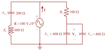
Chapter 17, Problem 5P
For the network in Fig. 17.42:
a. Find the current I.
b. Find the voltage VC.
c. Find the average power delivered to the network.
Expert Solution & Answer
Want to see the full answer?
Check out a sample textbook solution
Students have asked these similar questions
1a. Measure Vrms and Irms across ZLoad. Insert a capture of your circuit with the probes and readings.
1b. Measure the Average Power and the Power Factor for ZLoad. Insert a capture of yourcircuit with the Wattmeter and readings.
When the waveform shown in fig. (1) is applied to true responding ac voltmeter, the output would be (5.314 V). If the same signal is applied to average responding ac voltmeter, what will be:
1. The indicate value.
2. The true value.
3. The true form factor.
4. The indicate crest factor.
Problem 4
An electric saw, a wood shaper, and a motor load of a workshop establish a 18 kVA power demand at 0.5
power factor lagging on a 208 V, 60 Hz supply.
a) Establish the power triangle for the load.
b) Determine the power-factor capacitor that must be place in parallel with the load to raise the power
factor to 0.9 lagging.
c) Determine the change in supply current from the uncompensated to the compensated system.
d) Determine the power-factor capacitor that must be placed in parallel with the load to raise the power
factor to unity.
Chapter 17 Solutions
Introductory Circuit Analysis (13th Edition)
Ch. 17 - For theseries-parallel network in Fig.17.38. a....Ch. 17 - For the network in Fig. 17.39: a. Find the total...Ch. 17 - For the network in FIg. 17.40: a. Find the total...Ch. 17 - For the network in Fig. 17.41: a. Find the total...Ch. 17 - For the network in Fig. 17.42: a. Find the current...Ch. 17 - For the network in Fig. 17.43: a. Find the current...Ch. 17 - For the network in Fig. 17.44: a. Find the current...Ch. 17 - For the network in Fig. 17.45: a. Find the source...Ch. 17 - For the network of Fig. 17.46: a. Find the voltage...Ch. 17 - For the network in Fig. 17.47: a. Find the total...
Ch. 17 - For the network in Fig. 17.48: a. Find the total...Ch. 17 - For the network of Fig. 17.49: a. Find the total...Ch. 17 - For the network of Fig. 17.50: a. Find the total...Ch. 17 - Find the current I5 for the network in Fig. 17.51....Ch. 17 - Find the average power delivered to R5 in Fig....Ch. 17 - For the ladder network of Fig. 17.53: a. Find the...Ch. 17 - Prob. 17PCh. 17 - PSpice or Multisim For Problems 15 through 18, use...Ch. 17 - PSpice or Multisim For Problems 15 through 18, use...Ch. 17 - PSpice or Multisim For Problems 15 through 18, use...Ch. 17 - PSpice or Multisim For Problems 15 through 18, use...
Additional Engineering Textbook Solutions
Find more solutions based on key concepts
Assume a telephone signal travels through a cable at two-thirds the speed of light. How long does it take the s...
Electric Circuits (10th Edition)
Design an ideal inverting op-amp circuit such that the voltage gain is Av=25 . The maximum current in any resis...
Microelectronics: Circuit Analysis and Design
What is the color code for a 365- five-band precision resistor with a tolerance of 5 percent?
ELECTRICITY FOR TRADES (LOOSELEAF)
The current source in the circuit shown generates the current pulse
Find (a) v (0); (b) the instant of time gr...
Electric Circuits. (11th Edition)
Does the severity of an electric shock increase ordecrease with eh of the following changes? a. A decrease in t...
Electric Motors and Control Systems
A constant voltage of 10V is applied to a 50H inductance, as shown in Figure P3.51 Figure P3 51 The current in ...
Electrical Engineering: Principles & Applications (7th Edition)
Knowledge Booster


Learn more about
Need a deep-dive on the concept behind this application? Look no further. Learn more about this topic, electrical-engineering and related others by exploring similar questions and additional content below.Similar questions
- 7. A power station has to meet the following load demand : 50 kW Load A between 10 A.M. and 6 P.M. Load B 30 kW between 6 P.M. and 10 P.M. Load C 20 kW between 4 P.M. and 10 A.M. Plot the daily load curve and determine (1) diversity factor (ii) units generated per day (i) load factor.arrow_forwardCalculate the value of the ZL load required for maximum power transfer to the load.arrow_forwardA network is supplied by a 120 V rms, 60-Hz voltage source. An ammeter and a wattmeter indicate that 12 A rms is drawn from the source and 800 W are consumed by the network. Determine: a. The network power factor b. The network phase angle c. The network impedance d. The equivalent resistance and reactance of the networkarrow_forward
- Determine the complex power absorbed by the load in additionarrow_forwardThe variation of the load is considered over a period of month in the monthly load curve. Select one: True Falsearrow_forwardAfter studding the network answer the questions. 1. Find Is. 2. Find the current passing through the capacitor 3. Find the average power delivered to each element. 4. Find the reactive power for each element. 5. Find the apparent power for each element. 6. Find the total number of watts, volt-amperes reactive, and volt-amperes of the circuit. 7. Find the power factor for the system. 8. Sketch the power triangle. R E = 50 V Z60° 10 Ω 4 0 f = 60 Hzarrow_forward
- Problem 3 A climate control system, a motor load, and a lightning circuit of a small warehouse establish a 20- kVA power demand at 0.587 power factor lagging on a 240 V, 60 Hz supply. a) Establish the power triangle for the load. b) Determine the power-factor capacitor that must be placed in parallel with the load to raise the power factor to 0.865 lagging. c) Determine the change in supply current from the uncompensated to the compensated system. Explain.arrow_forward1- Determine YT and ZT 2- Sketch the admittance diagram. 3- Find E and IL. 4- Compute the power factor of the network and the power delivered to the network 5- Determine the equivalent series circuit as far as the terminal charac-teristics of the network are concerned. 6- Using the equivalent circuit developed in part e, calculate E, and compare it with the result of part c. 7- Determine the power delivered to the network, and compare it with the solution of part (d). 8- Determine the equivalent parallel network from the equivalent series circuit, and calculate the total admittance Yr. Compare the result with the solution of part (a). i= √2 (12) sin 1000r ZT R₁100 R₂40 L₁6 mH L12 mH 80 μF 20 µFarrow_forward25) Which one of the following is true of ac circuits with reactive elements? 25) A) The magnitude of the voltage across any one element can never exceed the applied voltage. B) The smaller the resistive element of a circuit, the closer the power factor is to unity. C) Depending on the frequency applied, the circuit can look either inductive or capacitive. D) The impedance of any one element can never exceed the total network impedance.arrow_forward
- From the circuit, determine the value of load z for maximum power transfer and the maximum average power transferred.arrow_forwardA. Find the average power absorbed by the load in the circuit. Use positive value if the power is absorbed and negative value if the power is delivered. B. Find the reactive power absorbed by the load. Use positive value if the reactive power is absorbed and negative value if the reactive power is delivered. C. Find the apparent power for the load.arrow_forwardProblem 4 An electric saw, a wood shaper, and a motor load of a workshop establish a 18 kVA power demand at 0.5 power factor lagging on a 208 V, 60 Hz supply. d) Determine the power-factor capacitor that must be placed in parallel with the load to raise the power factor to unity.arrow_forward
arrow_back_ios
SEE MORE QUESTIONS
arrow_forward_ios
Recommended textbooks for you
 Introductory Circuit Analysis (13th Edition)Electrical EngineeringISBN:9780133923605Author:Robert L. BoylestadPublisher:PEARSON
 Delmar's Standard Textbook Of ElectricityElectrical EngineeringISBN:9781337900348Author:Stephen L. HermanPublisher:Cengage Learning
 Programmable Logic ControllersElectrical EngineeringISBN:9780073373843Author:Frank D. PetruzellaPublisher:McGraw-Hill Education
 Fundamentals of Electric CircuitsElectrical EngineeringISBN:9780078028229Author:Charles K Alexander, Matthew SadikuPublisher:McGraw-Hill Education
 Electric Circuits. (11th Edition)Electrical EngineeringISBN:9780134746968Author:James W. Nilsson, Susan RiedelPublisher:PEARSON
 Engineering ElectromagneticsElectrical EngineeringISBN:9780078028151Author:Hayt, William H. (william Hart), Jr, BUCK, John A.Publisher:Mcgraw-hill Education,
Introductory Circuit Analysis (13th Edition)
Electrical Engineering
ISBN:9780133923605
Author:Robert L. Boylestad
Publisher:PEARSON
Delmar's Standard Textbook Of Electricity
Electrical Engineering
ISBN:9781337900348
Author:Stephen L. Herman
Publisher:Cengage Learning
Programmable Logic Controllers
Electrical Engineering
ISBN:9780073373843
Author:Frank D. Petruzella
Publisher:McGraw-Hill Education
Fundamentals of Electric Circuits
Electrical Engineering
ISBN:9780078028229
Author:Charles K Alexander, Matthew Sadiku
Publisher:McGraw-Hill Education
Electric Circuits. (11th Edition)
Electrical Engineering
ISBN:9780134746968
Author:James W. Nilsson, Susan Riedel
Publisher:PEARSON
Engineering Electromagnetics
Electrical Engineering
ISBN:9780078028151
Author:Hayt, William H. (william Hart), Jr, BUCK, John A.
Publisher:Mcgraw-hill Education,
Nodal Analysis for Circuits Explained; Author: Engineer4Free;https://www.youtube.com/watch?v=f-sbANgw4fo;License: Standard Youtube License