
Introductory Circuit Analysis (13th Edition)
13th Edition
ISBN: 9780133923605
Author: Robert L. Boylestad
Publisher: PEARSON
expand_more
expand_more
format_list_bulleted
Concept explainers
Videos
Textbook Question
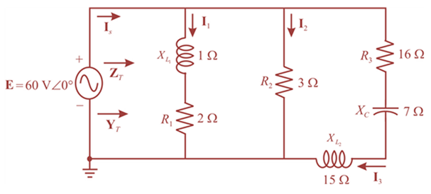
Chapter 17, Problem 10P
For the network in Fig. 17.47:
a. Find the total impedance ZT and the admittance YT.
b. Find the current I1, I2, an I3.
c. Verify Kirchhoff’s current law by showing that
d. Find the power factor of the network, and indicate whether it is leading or lagging.
Expert Solution & Answer
Want to see the full answer?
Check out a sample textbook solution
Students have asked these similar questions
1- Determine YT and ZT
2- Sketch the admittance diagram.
3- Find E and IL.
4- Compute the power factor of the network and the power
delivered to the network
5- Determine the equivalent series circuit as far as the terminal
charac-teristics of the network are concerned.
6- Using the equivalent circuit developed in part e, calculate E,
and compare it with the result of part c.
7- Determine the power delivered to the network, and
compare it with the solution of part (d).
8- Determine the equivalent parallel network from the
equivalent series circuit, and calculate the total admittance
Yr. Compare the result with the solution of part (a).
i= √2 (12) sin 1000r
ZT
R₁100 R₂40 L₁6 mH L12 mH
80 μF
20 µF
What should ZL be for the maximum power transfer in the circuit given below and calculate the maximum power
The z-parameters Z11, Z12, Z21, and z22 are measured in
a. A/A
b. V/V
C. A/V
d. V/A
Chapter 17 Solutions
Introductory Circuit Analysis (13th Edition)
Ch. 17 - For theseries-parallel network in Fig.17.38. a....Ch. 17 - For the network in Fig. 17.39: a. Find the total...Ch. 17 - For the network in FIg. 17.40: a. Find the total...Ch. 17 - For the network in Fig. 17.41: a. Find the total...Ch. 17 - For the network in Fig. 17.42: a. Find the current...Ch. 17 - For the network in Fig. 17.43: a. Find the current...Ch. 17 - For the network in Fig. 17.44: a. Find the current...Ch. 17 - For the network in Fig. 17.45: a. Find the source...Ch. 17 - For the network of Fig. 17.46: a. Find the voltage...Ch. 17 - For the network in Fig. 17.47: a. Find the total...
Ch. 17 - For the network in Fig. 17.48: a. Find the total...Ch. 17 - For the network of Fig. 17.49: a. Find the total...Ch. 17 - For the network of Fig. 17.50: a. Find the total...Ch. 17 - Find the current I5 for the network in Fig. 17.51....Ch. 17 - Find the average power delivered to R5 in Fig....Ch. 17 - For the ladder network of Fig. 17.53: a. Find the...Ch. 17 - Prob. 17PCh. 17 - PSpice or Multisim For Problems 15 through 18, use...Ch. 17 - PSpice or Multisim For Problems 15 through 18, use...Ch. 17 - PSpice or Multisim For Problems 15 through 18, use...Ch. 17 - PSpice or Multisim For Problems 15 through 18, use...
Knowledge Booster


Learn more about
Need a deep-dive on the concept behind this application? Look no further. Learn more about this topic, electrical-engineering and related others by exploring similar questions and additional content below.Similar questions
- Problem 1: Obtain the input impedance by replacing the linear transformer by its T equivalent. /100 802 Z 1402 252 m www /30 2002 -160arrow_forwardEMS TE A 25-KV motor absorbs 20 MVA at 0.8 pf lagging at rated terminal voltage. Using a base power of 100 MVA and a base voltage of 25 KV, find the per unit impedance of the motor. Select one: t of O a. 0.3125 <-36.87 deg. (p.u) O b. 0.2 <-36.87 deg. (p.u) estion Oc 2<53.13 deg (p.u) Od. None of these Oe. 0.16 <-36.87 deg. (p.u)arrow_forwardデジタル形式で段階的に解決 ありがとう!! SOLVE STEP BY STEP IN DIGITAL FORMAT 8. For the circuit in the figure: a) Determine the total admittance and impedance in polar form. b) Determine the value of C in microfarads and L in henries. c) Determine the voltage E and the currents IR, IL and IC in phasor form. d) Verify Kirchhoff's current law at a node. e) Determine the power supplied to the circuit. f) Determine the power factor of the circuit, and indicate whether it is leading or lagging. i, = 3 sen(3771 +60°)(D R1.2 XL 20 Xc 50arrow_forward
- Calculate the average and the root-mean-square value of the output voltage for the network in the figure below. Assume (VDI=VD2=0.5V) 10 V D2. D1 2k2 I t 3k2 3 k2 O 2.417V, 2.687V 2.421V, 2.736V 2.536V, 2.657V 2.173V, 2.824V O 2.517V, 2.876V O 2.714V, 2.766Varrow_forwardEvaluate the following twiddle factor: W48arrow_forwardFor a given power transfer which of the following is true. O Delta is associated with larger line voltage O Delta is associated with larger line current O Star is associated with larger line current O Conductors in delta system have smaller cross sectional area A Transformer having 1400 Primary turns connected to a 252 V a.c. supply. For a secondary Voltage of 416 V, the number of Secondary Turns should be No. of Turns in the Secondary hp fs 19 11 44 f10 & 7 8 V 60arrow_forward
- 9496 Reactance of a circuit is always expressed as real number and comprised the imaginary part of the impedance equation. O True O False "In phasor, the reactance has an angle of 0 degrees and the voltage and current are in phase." O True O Falsearrow_forwardJd [12] For the circuit shown find the load impedance, IL that absorbs the maximum aveerage Power claculate that Maximum average Power. -j4 jlor 822 42LR 52 | ZL #farrow_forward2. A three-phase transmission line has parameters Xc-6 k 2, R-3.25 2 and X₁-25 92, and delivers 300 MW to a load with both ends of the line at 230 kV. Draw a pi equivalent per-phase circuit of the line. On a per-phase basis, calculate the active power delivered to the load, the reactive power of the line and the active power delivered by the source. Based on these calculations can the equivalent circuit be simplified further?arrow_forward
- Three Impedances each of (14 – j18)N are connected in mesh across a three-phase 415V ac supply. Determine the phase current, line current, active power, reactive power drawn from supply. Also draw the Phasor diagram for the mesh connection and marks the Line current ,phase current line voltage and phase angle between phase current and pahse voltage. phase current (Ip) Line current real power reactive powerarrow_forwardChopper is feeding R-L load, V=200 V, R= 502, L=5 mH, f=1 kHz, D=0.5, E=0. Calculate: a. Imin & Imax. b. Average value for the load current. c. Time domain equations of load current iL1 (t) & i12 (t) ●arrow_forward8991 Reactance does not vary according to the frequency. True False Impedance always expressed as a real number and comprised the real part of impedance equation O True O Falsearrow_forward
arrow_back_ios
SEE MORE QUESTIONS
arrow_forward_ios
Recommended textbooks for you
 Power System Analysis and Design (MindTap Course ...Electrical EngineeringISBN:9781305632134Author:J. Duncan Glover, Thomas Overbye, Mulukutla S. SarmaPublisher:Cengage Learning
Power System Analysis and Design (MindTap Course ...
Electrical Engineering
ISBN:9781305632134
Author:J. Duncan Glover, Thomas Overbye, Mulukutla S. Sarma
Publisher:Cengage Learning
How do Electric Transmission Lines Work?; Author: Practical Engineering;https://www.youtube.com/watch?v=qjY31x0m3d8;License: Standard Youtube License