
Introductory Circuit Analysis (13th Edition)
13th Edition
ISBN: 9780133923605
Author: Robert L. Boylestad
Publisher: PEARSON
expand_more
expand_more
format_list_bulleted
Concept explainers
Videos
Textbook Question
Chapter 17, Problem 12P
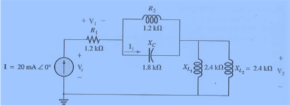
For the network of Fig. 17.49:
a. Find the total impedance ZT.
b. Find the voltage V1 in phasor form.
c. Find the current I1 in phasor form.
d. Find the voltage V2 in phasor form.
e. Find the source voltage Vs in phasor form.
Expert Solution & Answer
Want to see the full answer?
Check out a sample textbook solution
Students have asked these similar questions
In RLC series circuit, if the voltage across capacitor is greater than voltage across inductor, then power factor of the network is
a.
Unity.
b.
Zero.
c.
Leading.
d.
Lagging.
1. Explain the difference between the AC and DC? Give examples
2. Explain how RC and RL works in a circuit?
A circuit consists of an AC voltage source, a 10-ohm resistor, and a capacitor, all connected in series. The magnitude of the impedance of the capacitor is also 10 ohms. Which of the following is true about the phase angle difference between the source voltage and the current through the circuit?
a. Insufficient information is given.
b. The phase angle difference will be zero degrees.
c. The phase angle difference will be 45 degrees.
d. The phase angle difference will be 90 degrees.
Chapter 17 Solutions
Introductory Circuit Analysis (13th Edition)
Ch. 17 - For theseries-parallel network in Fig.17.38. a....Ch. 17 - For the network in Fig. 17.39: a. Find the total...Ch. 17 - For the network in FIg. 17.40: a. Find the total...Ch. 17 - For the network in Fig. 17.41: a. Find the total...Ch. 17 - For the network in Fig. 17.42: a. Find the current...Ch. 17 - For the network in Fig. 17.43: a. Find the current...Ch. 17 - For the network in Fig. 17.44: a. Find the current...Ch. 17 - For the network in Fig. 17.45: a. Find the source...Ch. 17 - For the network of Fig. 17.46: a. Find the voltage...Ch. 17 - For the network in Fig. 17.47: a. Find the total...
Ch. 17 - For the network in Fig. 17.48: a. Find the total...Ch. 17 - For the network of Fig. 17.49: a. Find the total...Ch. 17 - For the network of Fig. 17.50: a. Find the total...Ch. 17 - Find the current I5 for the network in Fig. 17.51....Ch. 17 - Find the average power delivered to R5 in Fig....Ch. 17 - For the ladder network of Fig. 17.53: a. Find the...Ch. 17 - Prob. 17PCh. 17 - PSpice or Multisim For Problems 15 through 18, use...Ch. 17 - PSpice or Multisim For Problems 15 through 18, use...Ch. 17 - PSpice or Multisim For Problems 15 through 18, use...Ch. 17 - PSpice or Multisim For Problems 15 through 18, use...
Knowledge Booster


Learn more about
Need a deep-dive on the concept behind this application? Look no further. Learn more about this topic, electrical-engineering and related others by exploring similar questions and additional content below.Similar questions
- For the above circuit calculate: a) The impedance of the circuit. b) The voltage across the complete circuit. c) The voltage across each reactive component.arrow_forward1. A wye connected load has a 5< 20° ohm impedance per phase and is connected across a 120 V three phase source. Calculate the line current. 2. A wire carries a current i = 3cos314t A. What is the average current over 6 seconds? 3. A series circuit composed of a 0.2 henry inductor and a 74 micro farad capacitor is connected to a 60V variable frequency source. At what frequency is the current be 4 amperes with lagging power factor? 4. A resistor and a capacitor are connected in series across a supply of 250V. Where supply frequency is 50Hz the current in the circuit is 5A. When the supply frequency is 60H2, the current is 5.8A. Find the value of the capacitance. 5. Find the average power supplied by the source and average power absorbed by the resistor. ww S/20° V -/20 6. Find I, in the circuit. j40 150/20 V ww wwarrow_forwardImpedance of AC circuit and Admittance of AC circuitSHOW THE CIRCUIT USING ANY SOFTWARE OR YOU CAN DRAW IT MANUAALYY thNAKSSarrow_forward
- Which component of impedance is not dependent on the frequency of the source of voltage? A. capacitance reactance B. inductive reactance C. resistance D. all are independent of the frequency of the sourcearrow_forwardFor the given circuit: a.Find the total impedance ZTin polar form. b.Find the current I and the voltages VRand VLin phasor form. c.Find the power factor of the circuit, and indicate whether it is leading or lagging.arrow_forwardIf A = 20260° and B= 5230°, find the products AB and BB".arrow_forward
- When a resistor is connected across the terminals of an ac generator (117 V) that has a fixed frequency, there is a current of 0.332 A in the resistor. When an inductor is connected across the terminals of the same generator, there is a current of 0.365 A in the inductor. When both the resistor and the inductor are connected in series between the terminals of this generator, what is (a) the impedance of the series combination and (b) the phase angle between the current and the voltage of the generator? Note: The ac current and voltage are rms values and power is an average value unless indicated otherwise. (a) Number (b) Number Buda i Vrms R Irms.R Circuit 1 Units Units Vrms. Irms, L Circuit 2 > L Vrms R www Circuit 3arrow_forwardQUESTION 50 RG180B/U is a coaxial cable with a nominal impedance of 95 02 and a capacitance per foot of 15.5 pF/ foot. Determine the inductance per foot of this cable. O a. 140 nH/ft Ob.45 nH/ft O c. 95 nH/ft O d.250 nH/ftarrow_forwardPHASE DIFFERENCE FIND( NEED NEAT HANDWRITTEN SOLUTION ONLY OTHERWISE DOWNVOTE).arrow_forward
- "If lab is equal to 595.8252306 and lb is 344296, the phase sequence is:" O POSITIVE O NEGATIVEarrow_forward2. In your own words, explain : a. What is reactive power? b. What is average power? c. What is instantaneous power? 3. For Fig 1 is shown a pure resistive circuit. Discovery wave-generator values and resistors acquired with your components kit. Average power must be P=13mW. Vin must be less than 5Vpp. Choose one value and get the Vrms for your calculations. Design the circuit according to your Analog Vin= Vrms 1000 Hz R1 0° Fig 1 a. What is R1 value? b. What is Vp value? What is Vpp value? С. d. What is Vrms value? e. Show your calculations and equations used.arrow_forwardc) Three identical inductors are connected in Y-across a three-phase 400V/50Hz line. The line current 12 A. The inductance of each inductor is o o o o 106.1 mH 19.25 H 61.26 mH. 183.8 mHarrow_forward
arrow_back_ios
SEE MORE QUESTIONS
arrow_forward_ios
Recommended textbooks for you
 Introductory Circuit Analysis (13th Edition)Electrical EngineeringISBN:9780133923605Author:Robert L. BoylestadPublisher:PEARSON
 Delmar's Standard Textbook Of ElectricityElectrical EngineeringISBN:9781337900348Author:Stephen L. HermanPublisher:Cengage Learning
 Programmable Logic ControllersElectrical EngineeringISBN:9780073373843Author:Frank D. PetruzellaPublisher:McGraw-Hill Education
 Fundamentals of Electric CircuitsElectrical EngineeringISBN:9780078028229Author:Charles K Alexander, Matthew SadikuPublisher:McGraw-Hill Education
 Electric Circuits. (11th Edition)Electrical EngineeringISBN:9780134746968Author:James W. Nilsson, Susan RiedelPublisher:PEARSON
 Engineering ElectromagneticsElectrical EngineeringISBN:9780078028151Author:Hayt, William H. (william Hart), Jr, BUCK, John A.Publisher:Mcgraw-hill Education,
Introductory Circuit Analysis (13th Edition)
Electrical Engineering
ISBN:9780133923605
Author:Robert L. Boylestad
Publisher:PEARSON
Delmar's Standard Textbook Of Electricity
Electrical Engineering
ISBN:9781337900348
Author:Stephen L. Herman
Publisher:Cengage Learning
Programmable Logic Controllers
Electrical Engineering
ISBN:9780073373843
Author:Frank D. Petruzella
Publisher:McGraw-Hill Education
Fundamentals of Electric Circuits
Electrical Engineering
ISBN:9780078028229
Author:Charles K Alexander, Matthew Sadiku
Publisher:McGraw-Hill Education
Electric Circuits. (11th Edition)
Electrical Engineering
ISBN:9780134746968
Author:James W. Nilsson, Susan Riedel
Publisher:PEARSON
Engineering Electromagnetics
Electrical Engineering
ISBN:9780078028151
Author:Hayt, William H. (william Hart), Jr, BUCK, John A.
Publisher:Mcgraw-hill Education,
How do Electric Transmission Lines Work?; Author: Practical Engineering;https://www.youtube.com/watch?v=qjY31x0m3d8;License: Standard Youtube License