
Introductory Circuit Analysis (13th Edition)
13th Edition
ISBN: 9780133923605
Author: Robert L. Boylestad
Publisher: PEARSON
expand_more
expand_more
format_list_bulleted
Concept explainers
Videos
Textbook Question
Chapter 17, Problem 4P
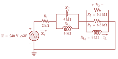
For the network in Fig. 17.41:
a. Find the total impedance ZT.
b. Calculate the voltage V2 and the current IL.
c. Find the power factor of the network.
Expert Solution & Answer
Want to see the full answer?
Check out a sample textbook solution
Students have asked these similar questions
A 400 V of 50 Hz is supplying a three-phase load of 150kW that is located 150 m away
from the distribution board. It is operated with two other power circuits in the ground
of soil resistivity of 1.2 °C.m/W at a depth of 0.8 m in a temperature of 30 °C. Find the
size of Cu power cable which is required for this load by attaching relevant tables from
Internet.
DB
150m
150 kW
LOAD
For the network of the next picture:
a. Determine the total impedance ZT.
b. Calculate the voltage V2 and the current IL.
c. Determine the potency factor of the network.
b.
In a transmission network of AIT Open University, a purely capacitive
impedance of -j300 Ohms placed in parallel with two 300 Ohms
receivers. The University need you to determine both the input
impedance and the power delivered to each receiver.
Use the below for your computation.
300 a
Z-300 2, v-2.5 10 m
300 2
(Rof receiver)
100 MH
Chapter 17 Solutions
Introductory Circuit Analysis (13th Edition)
Ch. 17 - For theseries-parallel network in Fig.17.38. a....Ch. 17 - For the network in Fig. 17.39: a. Find the total...Ch. 17 - For the network in FIg. 17.40: a. Find the total...Ch. 17 - For the network in Fig. 17.41: a. Find the total...Ch. 17 - For the network in Fig. 17.42: a. Find the current...Ch. 17 - For the network in Fig. 17.43: a. Find the current...Ch. 17 - For the network in Fig. 17.44: a. Find the current...Ch. 17 - For the network in Fig. 17.45: a. Find the source...Ch. 17 - For the network of Fig. 17.46: a. Find the voltage...Ch. 17 - For the network in Fig. 17.47: a. Find the total...
Ch. 17 - For the network in Fig. 17.48: a. Find the total...Ch. 17 - For the network of Fig. 17.49: a. Find the total...Ch. 17 - For the network of Fig. 17.50: a. Find the total...Ch. 17 - Find the current I5 for the network in Fig. 17.51....Ch. 17 - Find the average power delivered to R5 in Fig....Ch. 17 - For the ladder network of Fig. 17.53: a. Find the...Ch. 17 - Prob. 17PCh. 17 - PSpice or Multisim For Problems 15 through 18, use...Ch. 17 - PSpice or Multisim For Problems 15 through 18, use...Ch. 17 - PSpice or Multisim For Problems 15 through 18, use...Ch. 17 - PSpice or Multisim For Problems 15 through 18, use...
Additional Engineering Textbook Solutions
Find more solutions based on key concepts
Assume a telephone signal travels through a cable at two-thirds the speed of light. How long does it take the s...
Electric Circuits (10th Edition)
Analog Voltmeter Design Figure P2-98(a) shows a voltmeter circuit consisting of a D'Arsonval meter, two series ...
ANALYSIS+DESIGN OF LINEAR CIRCUITS(LL)
The voltage source of the circuit shown in Fig. P1.29 is given by s(t)=25cos(4104t45)(V). Obtain an expression ...
Fundamentals of Applied Electromagnetics (7th Edition)
With respect to the circuit in Fig. 5.90, (a) employ Thévenin’s theorem to determine the equivalent network see...
Loose Leaf for Engineering Circuit Analysis Format: Loose-leaf
A constant voltage of 10V is applied to a 50H inductance, as shown in Figure P3.51 Figure P3 51 The current in ...
Electrical Engineering: Principles & Applications (7th Edition)
What is the color code for a 365- five-band precision resistor with a tolerance of 5 percent?
ELECTRICITY FOR TRADES (LOOSELEAF)
Knowledge Booster


Learn more about
Need a deep-dive on the concept behind this application? Look no further. Learn more about this topic, electrical-engineering and related others by exploring similar questions and additional content below.Similar questions
- What should ZL be for the maximum power transfer in the circuit given below and calculate the maximum powerarrow_forwardIn a power system, which one of the following is not a state variable: Select one: O a. None of these O b. Voltage magnitude O c. Line impedance O d. Relative phase angle at the system nodesarrow_forward25) Which one of the following is true of ac circuits with reactive elements? 25) A) The magnitude of the voltage across any one element can never exceed the applied voltage. B) The smaller the resistive element of a circuit, the closer the power factor is to unity. C) Depending on the frequency applied, the circuit can look either inductive or capacitive. D) The impedance of any one element can never exceed the total network impedance.arrow_forward
- 2. Given tie information appearing in Fig. dit, deteruine 12V a) Ic ) Rc C) RB Rc e Vc=cv d) VCE VCE B=80 IB=A0HAarrow_forwardFor a given power transfer which of the following is true. O Delta is associated with larger line voltage O Delta is associated with larger line current O Star is associated with larger line current O Conductors in delta system have smaller cross sectional area A Transformer having 1400 Primary turns connected to a 252 V a.c. supply. For a secondary Voltage of 416 V, the number of Secondary Turns should be No. of Turns in the Secondary hp fs 19 11 44 f10 & 7 8 V 60arrow_forwardA)Determine Zi, Zo, and Av for the networkarrow_forward
- Calculate the average and the root-mean-square value of the output voltage for the network in the figure below. Assume (VDI=VD2=0.5V) 10 V D2. D1 2k2 I t 3k2 3 k2 O 2.417V, 2.687V 2.421V, 2.736V 2.536V, 2.657V 2.173V, 2.824V O 2.517V, 2.876V O 2.714V, 2.766Varrow_forwardThe impedance Z in the balanced three-phase circuit in Fig. is 100 - j75 Ω. Find a) IAB, IBC and ICA, b) IaA, IbB and IcC, c) Iba, Icb, and Iac.arrow_forwardThe following table gives the parameters for a distribution system. This system a) Draw the frequency domain equivalent circuit b) Find the voltage across the load impedance c) Find the average, reactive and complex power of the system d) Calculate the power factor of the source e) What percentage of the average power is dissipated over the line and source impedances find it f) To make the power factor 1, find the value of the circuit element to be connected parallel to the load Parameter Source (rms) Frequency Source Phase Angle source internal impedance Line Impedance Line Length Load Impedance findfind itValue 12kV 60Hz 0 0,5+j0,5 Ω 0,02+j0,03 02/km 200km 55,5+j75,5 Ω Not. Solve this question in detail step by step and explain your requests in detailarrow_forward
- 102 www. Q.15: For the mutually coupled circuit shown: 1. Find the equivalent circuit? 2. Find the total average power delivered to the circuit? 20/00 v 4 2 J8 J4 S J16 Q (Ans.: P7=18W)arrow_forward1. A motor load consists of a resistance of 6 Ohms in series with an inductance of 12 mH. Assume 120Vac, 60 Hz supply. a. What is the complex impedance of the load? b. What is the ac current through this load? c. What is theta, the angle between voltage and current through this load? d. What is the power factor? e. What capacitance should be added in parallel with this load to correct the power factor to 1? f. What is the current from the supply when the power factor is corrected?arrow_forwardEMS TE A 25-KV motor absorbs 20 MVA at 0.8 pf lagging at rated terminal voltage. Using a base power of 100 MVA and a base voltage of 25 KV, find the per unit impedance of the motor. Select one: t of O a. 0.3125 <-36.87 deg. (p.u) O b. 0.2 <-36.87 deg. (p.u) estion Oc 2<53.13 deg (p.u) Od. None of these Oe. 0.16 <-36.87 deg. (p.u)arrow_forward
arrow_back_ios
SEE MORE QUESTIONS
arrow_forward_ios
Recommended textbooks for you
 Introductory Circuit Analysis (13th Edition)Electrical EngineeringISBN:9780133923605Author:Robert L. BoylestadPublisher:PEARSON
 Delmar's Standard Textbook Of ElectricityElectrical EngineeringISBN:9781337900348Author:Stephen L. HermanPublisher:Cengage Learning
 Programmable Logic ControllersElectrical EngineeringISBN:9780073373843Author:Frank D. PetruzellaPublisher:McGraw-Hill Education
 Fundamentals of Electric CircuitsElectrical EngineeringISBN:9780078028229Author:Charles K Alexander, Matthew SadikuPublisher:McGraw-Hill Education
 Electric Circuits. (11th Edition)Electrical EngineeringISBN:9780134746968Author:James W. Nilsson, Susan RiedelPublisher:PEARSON
 Engineering ElectromagneticsElectrical EngineeringISBN:9780078028151Author:Hayt, William H. (william Hart), Jr, BUCK, John A.Publisher:Mcgraw-hill Education,
Introductory Circuit Analysis (13th Edition)
Electrical Engineering
ISBN:9780133923605
Author:Robert L. Boylestad
Publisher:PEARSON
Delmar's Standard Textbook Of Electricity
Electrical Engineering
ISBN:9781337900348
Author:Stephen L. Herman
Publisher:Cengage Learning
Programmable Logic Controllers
Electrical Engineering
ISBN:9780073373843
Author:Frank D. Petruzella
Publisher:McGraw-Hill Education
Fundamentals of Electric Circuits
Electrical Engineering
ISBN:9780078028229
Author:Charles K Alexander, Matthew Sadiku
Publisher:McGraw-Hill Education
Electric Circuits. (11th Edition)
Electrical Engineering
ISBN:9780134746968
Author:James W. Nilsson, Susan Riedel
Publisher:PEARSON
Engineering Electromagnetics
Electrical Engineering
ISBN:9780078028151
Author:Hayt, William H. (william Hart), Jr, BUCK, John A.
Publisher:Mcgraw-hill Education,
Nodal Analysis for Circuits Explained; Author: Engineer4Free;https://www.youtube.com/watch?v=f-sbANgw4fo;License: Standard Youtube License