What is the maximum power transfer theorem or MPTT?
A resistive load will consume maximum power from a network when the load resistance is equal to the resistance of the network as viewed from the open-circuit terminals, with all energy sources removed leaving only the internal resistances. Physicist Moritz von Jacobi introduced the maximum power transfer theorem in 1940. Therefore, this theorem is also known as Jacobi's law.
Although this theorem is important for all branches of electrical engineering, it has limited applications in power distribution and transmission as it requires maximum efficiency and maximum power transfer. This theorem has 50% efficiency that is enough for communication networks because in these types of networks maximum power transfer is required with less priority to efficiency. In the operation of transmission lines and antennas, the problem of MMTT is crucial.
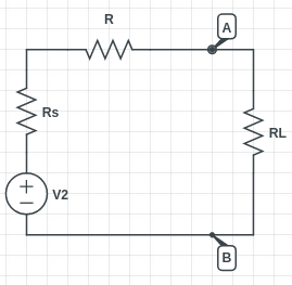
In the above circuit diagram, a load resistance RL is connected across terminals A and B of a network consisting of a voltage supply V2, its internal resistance Rs and internal resistance of connecting wires R. Let us assume Ri to be the sum of Rs and R i.e. total internal resistance or source resistance of the circuit after excluding load resistance RL.
According to the maximum power transfer theorem, RL will consume maximum power from the network when RL=Ri
Proof
Applying KVL in the circuit diagram above, we get
E=I(RL+Ri)
Circuit current
I=ERL+Ri
Power consumed by the load is
PL=I2RL=E2RL(RL+Ri)2
For PL to be maximum,
dPLdRL=0
Differentiating the above equation, we get
E2{(Rth+RL)2×1-RL×2(Rth+RL)(Rth+RL)4}=0⇒(Rth+RL)2-2RL(Rth+RL)=0⇒(Rth+RL)(Rth+RL-2RL)=0⇒(Rth-RL)=0⇒Rth=RL
∴ Maximum power is Pmax=E2RL4RL2=E24RL=E24Rth, since Rth=RL
Power transfer efficiency

If P is the power supplied to the load and Pt is the power supplied by the voltage source, then power transfer efficiency is given by η=PPt
The voltage source V2 provides power to both internal resistance Ri and load resistance RL.
The above diagram shows both η and Pmax in one graphical plot.
Efficiency η tends to be unity when RL=∞ and it has value of 0.5 when RL=Ri . This means at maximum power transfer the efficiency is 50%. In a communications system, this efficiency holds less importance as compared to a power system.
Importance of impedance matching
In case of mismatch of impedance between source impedance and load, the impedance will make the signal reflect the source causing destructive interference leading to reduced power transfer to the load. Impedance matching is used to design source to avoid this along with load impedances to reduce signal reflection and maximize power transfer. In DC circuits the source resistance and load resistance should be equal. In AC circuits the source impedance should be equal to either load impedance or complex conjugate of load impedance.
Maximum power transfer theorem in AC circuit
In the case of AC circuits, the internal impedance is (R1+jX1), and load impedance is (RL+jXL). In this case, the maximum power transfer (Pmax) will happen when the modulus of load impedance is equal to the modulus of internal impedance, i.e. |ZL|=|Z1|
In the case of variable load resistances, the maximum power transfer is obtained when the load impedance is the complex conjugate of internal impedance. For example, if the internal impedance is (R1+jX1), then for maximum power transfer the load impedance has to be (R1-jX1)
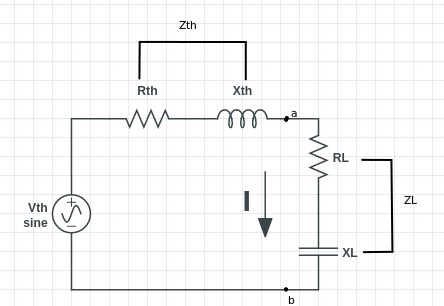
In AC circuits, maximum power transfer is achieved when load impedance (ZL) is equal to Thevenin equivalent impedance (Zth)
If Zth=Rth+jXth
then, ZL for max power = Rth-jXth
This means if the Thevenin impedance includes an inductor then the load impedance should have a capacitor for maximum power transfer condition as shown in the circuit diagram.
I=EthZth+ZL=Eth(Rth+RL)+j(Xth-XL)
For maximum power transfer, Xth should be equal to XL.
∴Eth(Rth+RL)+j(Xth-XL)=Eth(Rth+RL)
For maximum power transfer, Rth should also be equal to RL.
∴Eth(Rth+RL)=Eth2RthPL=IL2RL=(Eth2Rth)2RL=Eth24Rth2Rth=Eth24Rth=Pmax
Example question
In the given network, find the value of load resistor RL such that the maximum possible power will be transferred to RL. Using the maximum power transfer theorem, find also the value of the maximum power and the power supplied by the source under these conditions.
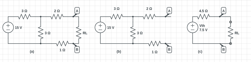
Looking at figure a, we need to remove the RL and find the Thevenin equivalent source for the circuit to the left of terminals A and B.
In figure b, Vth is equal to the drop across the vertical resistor 3Ω because current will not flow through the 02Ω and 1Ω resistors. Drop across each 3Ω resistor is given by,
Vth=152=7.5V , also known as the Thevenin voltage.
If we short circuit the 15V supply, then Thevenin resistance is given by,
Rth=2+1+(3||3)=4.5Ω
According to the maximum power transfer theorem, maximum power will take place when RL=Rth=4.5Ω
Maximum power drawn by RL is
2Vth4×RL=7.524×4.5=3.125W
Same amount of power is also developed in Rth, hence,
power supplied by source=3.125×2=6.25W
Context and Applications
The concept of maximum power transfer theorem is a fundamental of electrical network analysis and its knowledge is crucial in various diploma, undergraduate, and graduate degrees like:
- Bachelors of Technology (Electrical Engineering)
- Masters of Technology (Telecommunication Engineering)
- Bachelors of Science (Physics)
Practice Problems
Q1. To what does the application of Thevenin's theorem in circuit analysis lead?
- An ideal current source
- An ideal voltage source
- A voltage source with impedance in series
- A voltage source with impedance in parallel
Answer: c
Explanation: To find Thevenin equivalent in a circuit, we need to open the circuit, load terminals keeping the voltage source and impedance/resistance in series.
Q2. What should be the value of load resistance RL, if the Thevenin resistance is Rth, then to achieve maximum power?
- 0
- 1
- Rth
- ∝
Answer: c
Explanation: According to the maximum power transfer theorem, maximum power dissipation happens when the Thevenin resistance Rth is equal to load resistance RL.
Q3. What is the maximum efficiency at maximum power transfer in an electrical system?
- 30%
- 50%
- 70%
- 100%
Answer: b
Explanation: Maximum power transfer to load resistance happens at 50% efficiency.
Q4. What is required to find out what value of load resistance leads to maximum power dissipation?
- Open-circuit the load resistance terminals and find out the internal resistance of the circuit.
- Short-circuit the load resistance terminals and find out the internal resistance of the circuit.
- Find the sum of load resistance and internal resistance of the other elements.
- Find the sum of current going in and out of the load resistance.
Answer: a
Explanation: To find the load resistance value for maximum power dissipation, we need to open-circuit the terminals across load resistance and then find the internal resistance of the circuit.
Q5. How does reactance differ from impedance?
- Reactance is the sum of impedance and resistance.
- Impedance is from inductors and reactance is from capacitors.
- Reactance is the sum of resistance and impedance.
- Impedance is the sum of reactance and resistance.
Answer: d
Explanation: Reactance is the sum of the combined resistive effect of the inductor and capacitor in an AC circuit. Impedance is the sum of resistance and reactance. DC circuit does not have reactance, they only have resistance. The maximum power transfer theorem applies to both the AC circuit and DC circuit.
Related Concepts
- Thevenin's theorem
- Superposition theorem
- Voltage and current sources
- AC Network analysis
Want more help with your electrical engineering homework?
*Response times may vary by subject and question complexity. Median response time is 34 minutes for paid subscribers and may be longer for promotional offers.
Search. Solve. Succeed!
Study smarter access to millions of step-by step textbook solutions, our Q&A library, and AI powered Math Solver. Plus, you get 30 questions to ask an expert each month.
Electric Circuits and Networks
Circuit laws and method of analysis
Maximum power transfer theorem
Maximum power transfer theorem Homework Questions from Fellow Students
Browse our recently answered Maximum power transfer theorem homework questions.
Search. Solve. Succeed!
Study smarter access to millions of step-by step textbook solutions, our Q&A library, and AI powered Math Solver. Plus, you get 30 questions to ask an expert each month.