Concept explainers
For the resistive element in Fig. 15.81:
- Write the current in phasor form.
- Calculate the voltage across the resistor in phasor form.
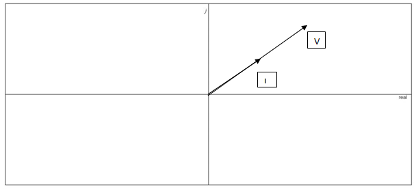
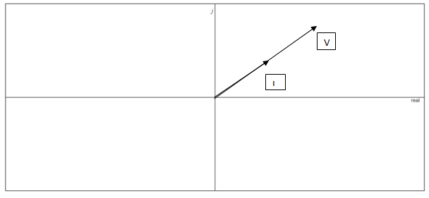
- Sketch the phasor diagram of the voltage and current.
- Write the voltage in the sinusoidal format.
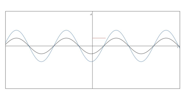
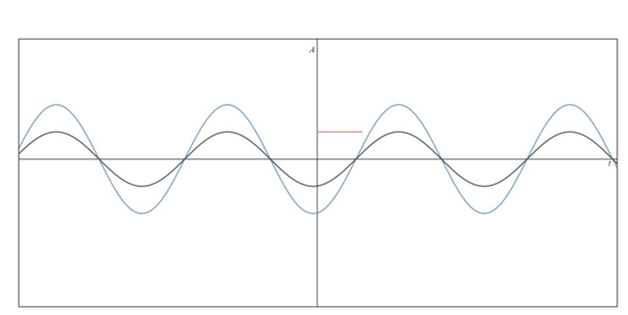
- Sketch the waveform of the voltage and current.

Fig. 15.81
(a)
The Current in phasor form.
Answer to Problem 1P
The current in phasor form is
Explanation of Solution
Given:
The sinusoidal expression of current is
The resistor value is
Concept Used:
In resistive element network, the network consists of only resistor element.
Resistor does not have any phase angle. It's purely real.
In this, the network current is in phase with voltage.
Total impedance
Current:
Calculation:
In order to convert to phasor form
Conclusion:
Hence, the current in phasor form is
(b)
Voltage across resistor in phasor form.
Answer to Problem 1P
Voltage across resistor in phasor form is
Explanation of Solution
Given:
The sinusoidal expression of current is
The resistor value is
Concept Used:
In resistive element network, the network consists of only resistor element.
Resistor does not have any phase angle. It's purely real.
In this network current are in phase with voltage.
Total impedance
Current:
Calculation:
We know that voltage across resistor is given by
Conclusion:
Hence, the voltage across resistor in phasor form is
(c)
Phasor diagram of the voltage and current.
Answer to Problem 1P
Phasor diagram of the voltage and current is drawn.

Explanation of Solution
Given:
The sinusoidal expression of current is
The resistor value is
Concept Used:
In resistive element network, the network consists of only resistor element.
Resistor does not have any phase angle. It's purely real.
In this, network current are in phase with voltage.
Total impedance
Current:
Calculation:
Based on the voltage and current value which is already obtained in above part the phasor diagram is drawn. From real axis the angle value is counted.

Conclusion:
Hence, the phasor diagram of the voltage and current is drawn.
(d)
Voltage in the sinusoidal expressions.
Answer to Problem 1P
Voltage in the sinusoidal expressions is
Explanation of Solution
Given:
The sinusoidal expression of current is
The resistor value is
Concept Used:
In resistive element network, the network consists of only resistor element.
Resistor does not have any phase angle. It's purely real.
In this, the network current is in phase with voltage.
Total impedance
Current:
Calculation:
In order to convert to sinusoidal form,
Conclusion:
Hence, voltage in the sinusoidal expressions is
(e)
Waveform of the voltage and current.
Answer to Problem 1P
Waveform of the voltage and current is drawn.

Explanation of Solution
Given:
The sinusoidal expression of current is
The resistor value is
Concept Used:
In resistive element network, the network consists of only resistor element.
Resistor does not have any phase angle. It's purely real.
In this, the network current is in phase with voltage.
Total impedance
Current:
Calculation:
Based on the voltage and current value which is already obtained in the above part, the waveform diagram is drawn. Here, A stands for amplitude.

Conclusion:
Hence, waveform of the voltage and current is drawn.
Want to see more full solutions like this?
Chapter 15 Solutions
Introductory Circuit Analysis (13th Edition)
Additional Engineering Textbook Solutions
Starting Out with Programming Logic and Design (5th Edition) (What's New in Computer Science)
Database Concepts (8th Edition)
Electric Circuits. (11th Edition)
Thermodynamics: An Engineering Approach
Modern Database Management
Automotive Technology: Principles, Diagnosis, And Service (6th Edition) (halderman Automotive Series)
- Instruction's: Q3 01: Required Handwritten Answer with explanation , Dont send Ai Answers , Straight Forward will be Reported to team & a detailed review will be done against that tutor for wasting the students time.arrow_forwardDon't use ai to answer I will report you answerarrow_forwardA periodic signal whose period is given by x(t) = Δ(t/τ), where τ = 1/20. The signal x(t) is band-limited by an ideal analog low-pass filter with a cutoff frequency fc. The signal x(t), ideally sampled at a rate of 80 Hz, is reconstructed using an ideal low-pass filter with a cutoff frequency of 40 Hz, resulting in the signal y(t). a) Plot the spectrum of y(t) if fc = 40 Hzb) Plot the spectrum of y(t) if fc = 20 Hzarrow_forward
- Q1 Q2 03 Find the total steel reinforcement (As) and the number of 20 mm bars that must be spread along the long direction of rectangular concrete footing of width B-2.10m which supports concrete column dimensions (0.4x 0.4) m. Given: D.L-900kN, L.L-800KN, qall-185kN/m², fc-21MPa, fy-400MPa. 300 450 Answer the following: A-Compare between the plate load test and standard penetration test, B-Define the disturbed samples, C- Find the depth of borehole for this case. B-2m. Dr=1.5m and qs =18ton/ m². The SPT records Versus depth are given in table below. Find qan for the raft foundation with B x B=10x10m and Df=2m, the allowable settlement is 50mm. 95 13 18 25arrow_forwardProject Statement A. It is required to introduce an additional load to cause maximum power transfer from the circuit below at the terminals a and b. The parallel loads resistances already connected are 50 Ω, 40 Ω, 30 Ω, 20 Ω, 10 Ω. 10 A 30022 w 8 Ω 5.2 Ω w w a + 500 V 12 Ω B. The circuit below is connected for long time to the terminal a and b of the circuit above after witch the switch is disconnected to allow the inductance system to discharge its stored energy. Determine the discharge current each τ and for 20 t and plot the current discharge behaviour. a 7 H 100 Ω 8 H 6H 10 H b C. Modify the 100 2 resistor or the inductor setup or both resistor and inductor setup to force the discharge current to be at least three times slower than in case B during the discharge. Your report must show the design steps and calculation then the relevant plots.arrow_forwardDraw the spectrum at the intermediate points and at the output of the cascaded systems. The input is x(t) = 6sinc(6t). The sampler operates at S = 12 Hz and performs ideal sampling. The cutoff frequency of the ideal low-pass filter is 5 Hz. X(t) → Sampler → Ideal Low-Pass Filter → Y(t)arrow_forward
- The signal x(t) is band-limited to 40 Hz and is modulated with a 320 Hz carrier, which generates y(t). This signal is then processed by a quadratic-law device that produces the output g(t) = y²(t). a) What is the minimum sampling rate for x(t) that avoids aliasing?b) What is the minimum sampling rate for y(t) that avoids aliasing?c) What is the minimum sampling rate for g(t) that avoids aliasing?arrow_forward1) Applying the bit mask to toggle the bits in positions 0 through 3 of the register AL, while passing through the bits in positions 7 through 4.What is the binary value of the AL after performing the following two instructions?MOV AL, 10111011 B;XOR AL, mask;arrow_forwardNeed a soluarrow_forward
- According to the book the answers are (а) 2.98 × 10⁻⁹ (b) 1.49 × 10⁻⁹arrow_forwardInstruction's: Q1: Required Handwritten Answer with explanation , Dont send Ai Answers , Straight Forward will be Reported to team & a detailed review will be done against that tutor for wasting the students time.arrow_forwardDon't use ai to answer I will report you answerarrow_forward
 Power System Analysis and Design (MindTap Course ...Electrical EngineeringISBN:9781305632134Author:J. Duncan Glover, Thomas Overbye, Mulukutla S. SarmaPublisher:Cengage Learning
