
Introductory Circuit Analysis (13th Edition)
13th Edition
ISBN: 9780133923605
Author: Robert L. Boylestad
Publisher: PEARSON
expand_more
expand_more
format_list_bulleted
Concept explainers
Videos
Textbook Question
Chapter 15, Problem 7P
For the capacitive element of Fig. 15.87:
- Calculate the reactance of the capacitor.
- Write the current in phasor form.
- Calculate the voltage across the capacitor in phasor form.
- Sketch the phasar diagram of the voltage and current.
- Write the voltage in the sinusoidal format.
- Sketch the waveform of the voltage and current.
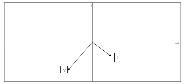
Fig. 15.87
Expert Solution & Answer
Want to see the full answer?
Check out a sample textbook solution
Students have asked these similar questions
Determine the capacitance value if the capacitive
reactance of 15 Kohms operates on a 40 Hz
supply.
a. 2.652 micro farad
O b. 26.52 micro farad
O c. 0.2652 MF
d. 0.2652 micro farad
What is the reactance of 3.00 microfarad capacitor? What is the impedance of the capacitor in series of 300 ohms?
Find the equivalent inductive reactance if the frequency is 65 Hz.
Chapter 15 Solutions
Introductory Circuit Analysis (13th Edition)
Ch. 15 - For the resistive element in Fig. 15.81: Write the...Ch. 15 - For the resistive element in Fig. 15.82: Write the...Ch. 15 - For the inductive element of Fig. 15.83: a. Write...Ch. 15 - For the inductive element of Fig. 15.84: Calculate...Ch. 15 - For the inductive element of Fig. 15.85: Write the...Ch. 15 - For the capacitive element of Fig. 15.86: Write...Ch. 15 - For the capacitive element of Fig. 15.87:...Ch. 15 - For the capacitive element of Fig. 15.88: Write...Ch. 15 - Sketch the impedance diagram of a 120 k resistor.Ch. 15 - Sketch the impedance diagram of a 5 mH coil...
Ch. 15 - Sketch the impedance diagram of a 0.02 F capacitor...Ch. 15 - Calculate the total impedance of the circuits in...Ch. 15 - Calculate the total impedance of the circuits in...Ch. 15 - Find the type and impedance in ohms of the series...Ch. 15 - For the circuit in Fig. 15.92 Find the total...Ch. 15 - Repeat problem 15 for the circuit in Fig. 15.93,...Ch. 15 - For the circuit in Fig. 15.94: Find the total...Ch. 15 - Repeat Problem 17 for the circuit in Fig. 15.95...Ch. 15 - For the circuit of Fig. 15.96: Find the total...Ch. 15 - For the circuit of Fig. 15.97: Find the current...Ch. 15 - Prob. 21PCh. 15 - Using the oscilloscope reading in Fig. 15.99,...Ch. 15 - Using the DMM current reading and the oscilloscope...Ch. 15 - Using the oscilloscope reading in Fig. 15.101:...Ch. 15 - An electrical load has a power factor of 0.8...Ch. 15 - Find the series element or elements that must be...Ch. 15 - Calculate the voltages V1andV2 for the circuits in...Ch. 15 - Calculate the voltages V1andV2 for the circuits in...Ch. 15 - For the circuit in Fig. 15.105: Determine...Ch. 15 - For the circuit in Fig. 15.106: a. Plot ZT and T...Ch. 15 - Prob. 31PCh. 15 - For the series R-L-C circuit in Fig. 15.108: Plot...Ch. 15 - For the series R-C circuit in Fig. 15.109:...Ch. 15 - For the circuit in Fig. 15.110, determine the...Ch. 15 - For the oscilloscope traces in Fig. 15.111:...Ch. 15 - For the network in Fig. 15.92 (usef=1kHz):...Ch. 15 - For the network in Fig. 15.93: Plot the impedance...Ch. 15 - For the network in Fig. 15.105: Find the rms...
Knowledge Booster


Learn more about
Need a deep-dive on the concept behind this application? Look no further. Learn more about this topic, electrical-engineering and related others by exploring similar questions and additional content below.Similar questions
- a)Find the mathematical expression of the capacitor voltage? b)calculate the average power on the resistorarrow_forwardAn inductor L is connected in parallel to the series combination of capacitor C and resistor R. If L = 0.02122 H, C = 0.000421 F and R = 5 Ω, the impressed voltage E = 120 volts AC. Find the following: a. Circuit Diagram, total impedance, total current. b. Determine the frequency at which the inductive reactance is equal to capacitive reactance. c. Determine the voltage drop across the capacitor and the Quality Factor Q.arrow_forwardDetermine the Inductance that has a Reactance of 2 KOhms, at a frequency of 14.47 KHz. show all the stepsarrow_forward
- b. 16 x 10 sim 10r + 2) 13. Determine the capacitive reactance (in ohms) of a 0.2 μF capacitor for a. de and for the following frequencies: b. 60 Hz se rooctance is given. c. 2 kHz d. 2 MHzarrow_forwardA capacitor has a reactance of 80 ohms when connected to a 50 Hz supply. Calculate the value of capacitance.a. 39.79 microfaradb. 39.97 microfaradc. 93.79 microfaradd. 93.97 microfaradKindly provide a CLEAR and COMPLETE solution.arrow_forwardPlease answer it in 30 mins. Show soln neat and complete. Thank you Capacitancearrow_forward
- When is the capacitive reactance (Xc) greater? a) If the capacitance is higher and the supply frequency is lower b) If the capacitance and supply frequency are lower C)If the capacitance and supply frequency are higher d) If the capacitance and supply frequency are higherarrow_forward58. Two capacitors, a 20 µF and a 30 µF, are connected in series to a 60-Hz source. What is the total capacitive reactance? a. 117.96 N b. 221.04 N c. 253.05 N d. 333.16 Narrow_forward10 V sine 90 kHz 1 kQ C1 1 nF 2. Using a Square function with 90,000 Hz in your function-generator, a 1000-ohm resistor, and a 1 nano-Farad capacitor, determine the charging time for the capacitor. Show your calculations and show the charging-discharge curve with an oscilloscope in TINKERCAD.arrow_forward
- a)calculate the magnitude of the voltage across the j9 ohm inductor.b) calculate the magnitude of the current through the -j15 ohm capacitor.arrow_forwardThrough a capacitor of capacitance 15 micro-farad with a frequency of 50 hz. Compute its reactancearrow_forwardFind the inductive reactance of a 50 uH and 25 uH connected in parallel subjected to a 47.74648292 Hz.arrow_forward
arrow_back_ios
SEE MORE QUESTIONS
arrow_forward_ios
Recommended textbooks for you
 Introductory Circuit Analysis (13th Edition)Electrical EngineeringISBN:9780133923605Author:Robert L. BoylestadPublisher:PEARSON
 Delmar's Standard Textbook Of ElectricityElectrical EngineeringISBN:9781337900348Author:Stephen L. HermanPublisher:Cengage Learning
 Programmable Logic ControllersElectrical EngineeringISBN:9780073373843Author:Frank D. PetruzellaPublisher:McGraw-Hill Education
 Fundamentals of Electric CircuitsElectrical EngineeringISBN:9780078028229Author:Charles K Alexander, Matthew SadikuPublisher:McGraw-Hill Education
 Electric Circuits. (11th Edition)Electrical EngineeringISBN:9780134746968Author:James W. Nilsson, Susan RiedelPublisher:PEARSON
 Engineering ElectromagneticsElectrical EngineeringISBN:9780078028151Author:Hayt, William H. (william Hart), Jr, BUCK, John A.Publisher:Mcgraw-hill Education,
Introductory Circuit Analysis (13th Edition)
Electrical Engineering
ISBN:9780133923605
Author:Robert L. Boylestad
Publisher:PEARSON
Delmar's Standard Textbook Of Electricity
Electrical Engineering
ISBN:9781337900348
Author:Stephen L. Herman
Publisher:Cengage Learning
Programmable Logic Controllers
Electrical Engineering
ISBN:9780073373843
Author:Frank D. Petruzella
Publisher:McGraw-Hill Education
Fundamentals of Electric Circuits
Electrical Engineering
ISBN:9780078028229
Author:Charles K Alexander, Matthew Sadiku
Publisher:McGraw-Hill Education
Electric Circuits. (11th Edition)
Electrical Engineering
ISBN:9780134746968
Author:James W. Nilsson, Susan Riedel
Publisher:PEARSON
Engineering Electromagnetics
Electrical Engineering
ISBN:9780078028151
Author:Hayt, William H. (william Hart), Jr, BUCK, John A.
Publisher:Mcgraw-hill Education,
03 - The Cartesian coordinate system; Author: Technion;https://www.youtube.com/watch?v=hOgKEplCx5E;License: Standard YouTube License, CC-BY