
Introductory Circuit Analysis (13th Edition)
13th Edition
ISBN: 9780133923605
Author: Robert L. Boylestad
Publisher: PEARSON
expand_more
expand_more
format_list_bulleted
Concept explainers
Videos
Textbook Question
Chapter 15, Problem 35P
For the oscilloscope traces in Fig. 15.111:
- Determine the phase relationship between the waveforms, and indicate which one leads or lags.
- Determine the peak-to-peak and rms values of each waveform.
- Find the frequency of each waveform.
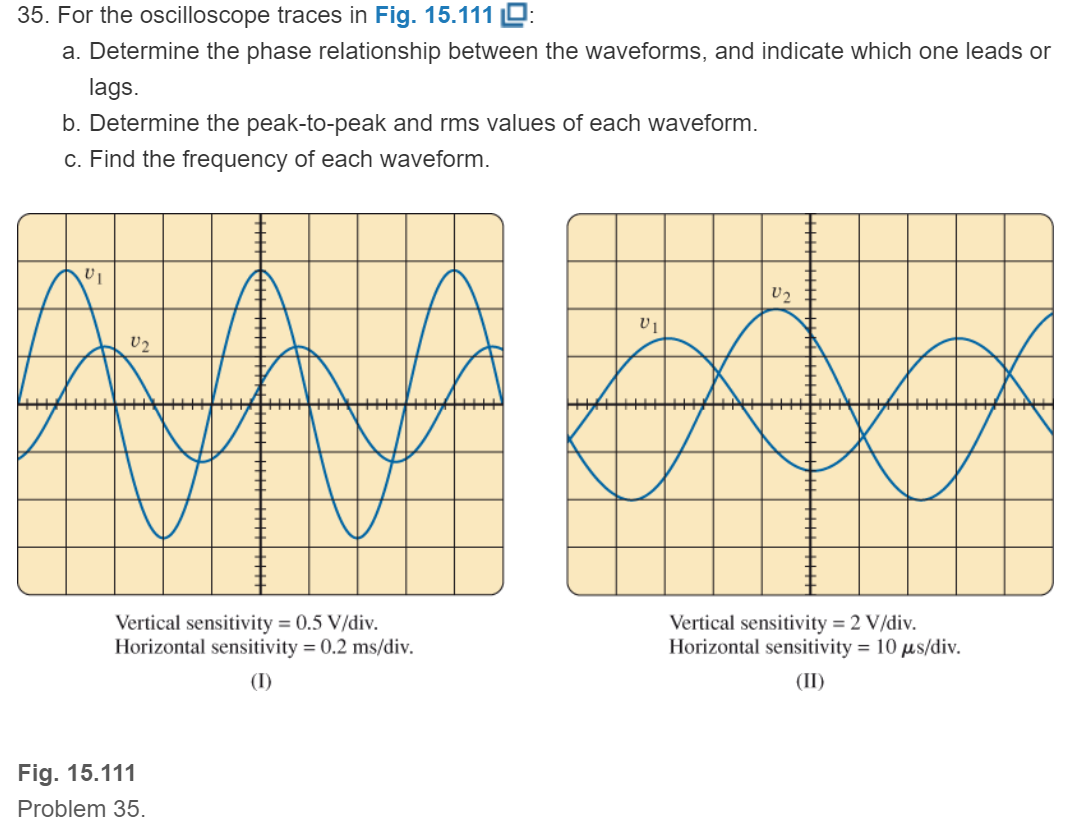
Fig. 15.111
Expert Solution & Answer
Want to see the full answer?
Check out a sample textbook solution
Students have asked these similar questions
Draw a sinusoidal waveform with a peak-to-peak voltage of 6 V and a frequency of 1kHz in an oscillogram showing the grid lines of an oscilloscope as shown below. Use 1V/div vertical division and 1ms/div horizontal division.
CRO cannot be used for measuring the Sinusoidal
waveform's frequency.
Select one:
True
O False
5 ms
(a) Vp
(b) Vp-P
(c) Frequency
(d) Period
(e) Angular Velocity
270 V
(f) Phase angle
(g) Equation of the waveform
115 V
Chapter 15 Solutions
Introductory Circuit Analysis (13th Edition)
Ch. 15 - For the resistive element in Fig. 15.81: Write the...Ch. 15 - For the resistive element in Fig. 15.82: Write the...Ch. 15 - For the inductive element of Fig. 15.83: a. Write...Ch. 15 - For the inductive element of Fig. 15.84: Calculate...Ch. 15 - For the inductive element of Fig. 15.85: Write the...Ch. 15 - For the capacitive element of Fig. 15.86: Write...Ch. 15 - For the capacitive element of Fig. 15.87:...Ch. 15 - For the capacitive element of Fig. 15.88: Write...Ch. 15 - Sketch the impedance diagram of a 120 k resistor.Ch. 15 - Sketch the impedance diagram of a 5 mH coil...
Ch. 15 - Sketch the impedance diagram of a 0.02 F capacitor...Ch. 15 - Calculate the total impedance of the circuits in...Ch. 15 - Calculate the total impedance of the circuits in...Ch. 15 - Find the type and impedance in ohms of the series...Ch. 15 - For the circuit in Fig. 15.92 Find the total...Ch. 15 - Repeat problem 15 for the circuit in Fig. 15.93,...Ch. 15 - For the circuit in Fig. 15.94: Find the total...Ch. 15 - Repeat Problem 17 for the circuit in Fig. 15.95...Ch. 15 - For the circuit of Fig. 15.96: Find the total...Ch. 15 - For the circuit of Fig. 15.97: Find the current...Ch. 15 - Prob. 21PCh. 15 - Using the oscilloscope reading in Fig. 15.99,...Ch. 15 - Using the DMM current reading and the oscilloscope...Ch. 15 - Using the oscilloscope reading in Fig. 15.101:...Ch. 15 - An electrical load has a power factor of 0.8...Ch. 15 - Find the series element or elements that must be...Ch. 15 - Calculate the voltages V1andV2 for the circuits in...Ch. 15 - Calculate the voltages V1andV2 for the circuits in...Ch. 15 - For the circuit in Fig. 15.105: Determine...Ch. 15 - For the circuit in Fig. 15.106: a. Plot ZT and T...Ch. 15 - Prob. 31PCh. 15 - For the series R-L-C circuit in Fig. 15.108: Plot...Ch. 15 - For the series R-C circuit in Fig. 15.109:...Ch. 15 - For the circuit in Fig. 15.110, determine the...Ch. 15 - For the oscilloscope traces in Fig. 15.111:...Ch. 15 - For the network in Fig. 15.92 (usef=1kHz):...Ch. 15 - For the network in Fig. 15.93: Plot the impedance...Ch. 15 - For the network in Fig. 15.105: Find the rms...
Knowledge Booster


Learn more about
Need a deep-dive on the concept behind this application? Look no further. Learn more about this topic, electrical-engineering and related others by exploring similar questions and additional content below.Similar questions
- b. 16 x 10 sim 10r + 2) 13. Determine the capacitive reactance (in ohms) of a 0.2 μF capacitor for a. de and for the following frequencies: b. 60 Hz se rooctance is given. c. 2 kHz d. 2 MHzarrow_forwardb)Find power for this waveform 2 /sec 0 1 2 3arrow_forwardIn an experiment, the oscilloscope displayed the figure below, determine the frequency of each waveform, and the phase shift between the two waveforms and which leads or lags. Vertical sensitivity = 0.5 V/div. Horizontal sensitivity = 1 ms/div. O 125 Hz (both), and e lags i by 107° O 25 Hz (both), and e leads i by 153° O 125 Hz (both), and e leads i by 207° O 125 Hz (both), and i leads e by 207° O 125 Hz (both), and e leads i by 53°arrow_forward
- A voltage wave of 250 kHz has a Vmax-5 V and Vmin=-35 V. The duty cycle of this wave is 0.875. This voltage waveform has been applied across a 2.5 µH inductor for a very long time so that steady state has been achieved. Diagrams of the wave parameters and circuit are shown in this figure: L What is the average voltage of this wave? Average voltage = 35 V Voltage (arb, unit) 1.25 Minimum current: -3.5€ Amps 1 0.75 0.5 0.25 0 4.25 05 Have you integrated the wave over full cycle? 4.75 4 -1.25 Vmax 0.5 Vmin What is the average current flowing through the inductor? Average current = 3.56 A 15 Period/s On average, there is no power consumed by the inductor. Have you considered this? What are the maximum and minimum currents that flow through the inductor? Maximum current: 0.50 Amps D= 25 TH TH Have you used the relationship for current and voltage in an inductor? Have you considered the slope of the current wave?arrow_forwardPlot the quiescent pointarrow_forward1.A sinusoidal voltage signal with a maximum magnitude of 1.0 V is superimposed on a 3.0 V DC voltage. i. Write down the total instantaneous value of the combined voltages. ii. Sketch the superimposed voltage and labeled its values.arrow_forward
- An rms voltage of 22.2 V with a frequencyof 1.00 kHz is applied to a 0.290-mH inductor. (a) What is the rmscurrent in this circuit? (b) By what factor does the current changeif the frequency of the voltage is doubled? (c) Calculate the current for a frequency of 2.00 kHzarrow_forward14. A technician uses an oscilloscope to measure the peak value of an AC wave. He tells you that the voltage has a peak value of 100 V. What is the RMS value of the voltage? A. 10 V B. 707 V C. 70.7 V D. 100 Varrow_forwardDetermine the Inductance that has a Reactance of 2 KOhms, at a frequency of 14.47 KHz. show all the stepsarrow_forward
- Segments of two sinusoids are shown in the plot below. Determine the phase difference between the two waveforms. Amplitude 0.5 0 -0.5 0 O 900° 00° 090° 0.5 1 Time (seconds) 1.5arrow_forwardAn alternating voltage e= 120 sin 314t is applied to a circuit in which an ohmic resistance of 30ohm is inserted and current flows through the circuit. 1. Analyze the average value of the voltage. 2. Analyze the maximum value of voltage. 3. Calculate the time period of the waveform. 4. Analyze the rms value of the voltage. 5. Determine the frequency of the waveform.arrow_forwardIn an experiment, the function generator is adjusted to generate a square voltage at a certain frequency. This voltage is displayed on an oscilloscope and the reading is 10 V peak-to-peak. The rms value of this voltage is .What will be the rms value of this voltage if the frequency is reduced to the half value? 3.536 Vrms . 3.536 Vrms O 5 Vrms . 1.7677 Vrms O 3.536 Vrms. 1.7677 Vrms O 5 Vrms . 5 Vrms ...... O 10 Vrms . 10 Vrms ......arrow_forward
arrow_back_ios
SEE MORE QUESTIONS
arrow_forward_ios
Recommended textbooks for you
 Introductory Circuit Analysis (13th Edition)Electrical EngineeringISBN:9780133923605Author:Robert L. BoylestadPublisher:PEARSON
 Delmar's Standard Textbook Of ElectricityElectrical EngineeringISBN:9781337900348Author:Stephen L. HermanPublisher:Cengage Learning
 Programmable Logic ControllersElectrical EngineeringISBN:9780073373843Author:Frank D. PetruzellaPublisher:McGraw-Hill Education
 Fundamentals of Electric CircuitsElectrical EngineeringISBN:9780078028229Author:Charles K Alexander, Matthew SadikuPublisher:McGraw-Hill Education
 Electric Circuits. (11th Edition)Electrical EngineeringISBN:9780134746968Author:James W. Nilsson, Susan RiedelPublisher:PEARSON
 Engineering ElectromagneticsElectrical EngineeringISBN:9780078028151Author:Hayt, William H. (william Hart), Jr, BUCK, John A.Publisher:Mcgraw-hill Education,
Introductory Circuit Analysis (13th Edition)
Electrical Engineering
ISBN:9780133923605
Author:Robert L. Boylestad
Publisher:PEARSON
Delmar's Standard Textbook Of Electricity
Electrical Engineering
ISBN:9781337900348
Author:Stephen L. Herman
Publisher:Cengage Learning
Programmable Logic Controllers
Electrical Engineering
ISBN:9780073373843
Author:Frank D. Petruzella
Publisher:McGraw-Hill Education
Fundamentals of Electric Circuits
Electrical Engineering
ISBN:9780078028229
Author:Charles K Alexander, Matthew Sadiku
Publisher:McGraw-Hill Education
Electric Circuits. (11th Edition)
Electrical Engineering
ISBN:9780134746968
Author:James W. Nilsson, Susan Riedel
Publisher:PEARSON
Engineering Electromagnetics
Electrical Engineering
ISBN:9780078028151
Author:Hayt, William H. (william Hart), Jr, BUCK, John A.
Publisher:Mcgraw-hill Education,
What is Filter & Classification of Filters | Four Types of Filters | Electronic Devices & Circuits; Author: SimplyInfo;https://www.youtube.com/watch?v=9x1Sjz-VPSg;License: Standard Youtube License