
Introductory Circuit Analysis (13th Edition)
13th Edition
ISBN: 9780133923605
Author: Robert L. Boylestad
Publisher: PEARSON
expand_more
expand_more
format_list_bulleted
Concept explainers
Videos
Textbook Question
Chapter 15, Problem 28P
Calculate the voltages
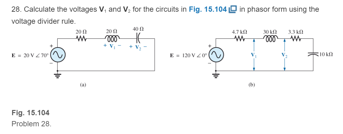
Fig. 15.104
Expert Solution & Answer
Want to see the full answer?
Check out a sample textbook solution
Students have asked these similar questions
15:24
A
2. Calculate the total resistance between the points A and B.
3
-www
4 ohm
|||
www
3 ohm
Qall 72%
V
1 ohm
ww
2 ohm
0
A JFET has a value of gmo = 4000 μS. Determine the value of gm at VGS = – 3V. Given that VGS (off) = – 8V.
For the following circuit, determine the maximum power, PMa in Watts that can be
transferred to the load resistor RL. Along the way you must find: (a) VTh, (b) RTh, and (c)
PMaz in Watts. You must show all your work to receive full or partial credit. Put your final
answers in the box provided.
15N
a
102 2A( T
RL
15V
Chapter 15 Solutions
Introductory Circuit Analysis (13th Edition)
Ch. 15 - For the resistive element in Fig. 15.81: Write the...Ch. 15 - For the resistive element in Fig. 15.82: Write the...Ch. 15 - For the inductive element of Fig. 15.83: a. Write...Ch. 15 - For the inductive element of Fig. 15.84: Calculate...Ch. 15 - For the inductive element of Fig. 15.85: Write the...Ch. 15 - For the capacitive element of Fig. 15.86: Write...Ch. 15 - For the capacitive element of Fig. 15.87:...Ch. 15 - For the capacitive element of Fig. 15.88: Write...Ch. 15 - Sketch the impedance diagram of a 120 k resistor.Ch. 15 - Sketch the impedance diagram of a 5 mH coil...
Ch. 15 - Sketch the impedance diagram of a 0.02 F capacitor...Ch. 15 - Calculate the total impedance of the circuits in...Ch. 15 - Calculate the total impedance of the circuits in...Ch. 15 - Find the type and impedance in ohms of the series...Ch. 15 - For the circuit in Fig. 15.92 Find the total...Ch. 15 - Repeat problem 15 for the circuit in Fig. 15.93,...Ch. 15 - For the circuit in Fig. 15.94: Find the total...Ch. 15 - Repeat Problem 17 for the circuit in Fig. 15.95...Ch. 15 - For the circuit of Fig. 15.96: Find the total...Ch. 15 - For the circuit of Fig. 15.97: Find the current...Ch. 15 - Prob. 21PCh. 15 - Using the oscilloscope reading in Fig. 15.99,...Ch. 15 - Using the DMM current reading and the oscilloscope...Ch. 15 - Using the oscilloscope reading in Fig. 15.101:...Ch. 15 - An electrical load has a power factor of 0.8...Ch. 15 - Find the series element or elements that must be...Ch. 15 - Calculate the voltages V1andV2 for the circuits in...Ch. 15 - Calculate the voltages V1andV2 for the circuits in...Ch. 15 - For the circuit in Fig. 15.105: Determine...Ch. 15 - For the circuit in Fig. 15.106: a. Plot ZT and T...Ch. 15 - Prob. 31PCh. 15 - For the series R-L-C circuit in Fig. 15.108: Plot...Ch. 15 - For the series R-C circuit in Fig. 15.109:...Ch. 15 - For the circuit in Fig. 15.110, determine the...Ch. 15 - For the oscilloscope traces in Fig. 15.111:...Ch. 15 - For the network in Fig. 15.92 (usef=1kHz):...Ch. 15 - For the network in Fig. 15.93: Plot the impedance...Ch. 15 - For the network in Fig. 15.105: Find the rms...
Knowledge Booster


Learn more about
Need a deep-dive on the concept behind this application? Look no further. Learn more about this topic, electrical-engineering and related others by exploring similar questions and additional content below.Similar questions
- For all problems, solve for the following a. Vgs b. Id 16V C. Zin d. Zout e. Av ¹3.9kQ V₁0 H 0.05 µF IMQ | 0.05 μF HF Joss - 6 MA Vp-3 V 1.6 k 40µFarrow_forward[Q3] Analyze the following electrical circuit with mesh analysis by finding the currents using Gauss-elimination method 10 Q 15 Q 25 0 20Q 35Q - 1000 V 1000V 2000 V 2000 V 30 2 40 Qarrow_forwardFor the circuit shown in the Figure, if Vs= 50 V and R = 105 Q, answer the following 2 questions: I com (A +V 3 KQ com 3 KO S6KO > 6 KO The reading of the ammeter A is: Oa. 15.84 mA Ob. 19.84 mA Oc. 17.84 mA Od. 21.84 mA The reading of the voltmeter V is: Оа. 3.9 V Ob. 2 V Ос. 3.12 V Od. 2.49 Varrow_forward
- Question 13 For the circuit shown, the following mesh currents are given: IA =1.24271.2° A IB =0.45Z49.0° A Ic = 0.75Z150.2° A What is the value of the voltage VB? j5n + 20 VB 62- 45° V j4 N VA 240° V Vc 5230° V O 2.484- 108.8° V O 2.48471.2 V O 2.23/66.8° V O 2.23Z- 113.2° Varrow_forwardXc R1 XL 60 10 Ω 12 Ω Zt For the above serial components calculate the total impedance - Zt Zt = %3Darrow_forwardZVO A VM ll l Ciassroo docs.google.com a Q1 For the following circuit diagram, 1 is .......... 50 15 V 12V 40 50 I2 70 60 90 12 a 4 A 1 O -1 احمد عصام احمد 8:00- äc lul 21.04.20 O Darrow_forward
- Which of the following is true for pure capacitive circuit? a. Current lags the voltage by 90 degree b. Voltage and current are inphase С. Voltage lags the current by 90 degree d. Voltage leads the current by 90 degree •A:Oarrow_forward5 52 13 -j12 5:1 j2 12 ww 50 20 V 20 VI For the circuit shown, the value of the primary side of the ideal transformer V1 is .V. * O 34<98.1 O 67<58.1 O 104<-67.3 O 72<-45.3 O 48<86.7 O63<-54.3 O 56.4<87.3 O none of the above wwarrow_forwardApplication of Complex Number Determine the values of L and C that will make the equivalent impedance across the source be a pure resistance of 250 ohms. Vs 60Hz 1000 16 сarrow_forward
- 16. Determine the following from the given R-L-C series circuit: i) Impedance Z ii) Current i iii) Voltage across resistance V iv) Voltage across inductance V₁ v) Voltage across capacitance Ve vi) Total power delivered vii) Power factor 70.7 sheet Ⓒ 40 R = 30 X₁70 X 30 www vooarrow_forwardK/s l 3:34 يستخدم التطبيق المیکروفون Me et 23 docs.google.com/forms 04: For the circuit shown below find vj. Vz. V3 and v 12 V3 4Ω 3 A 5Ω 12 ) 2 A 20 Ω 2 A wwarrow_forwardV 2A 8A 10 ohm O _60 O 40 O _40 60arrow_forward
arrow_back_ios
SEE MORE QUESTIONS
arrow_forward_ios
Recommended textbooks for you
 Power System Analysis and Design (MindTap Course ...Electrical EngineeringISBN:9781305632134Author:J. Duncan Glover, Thomas Overbye, Mulukutla S. SarmaPublisher:Cengage Learning
Power System Analysis and Design (MindTap Course ...
Electrical Engineering
ISBN:9781305632134
Author:J. Duncan Glover, Thomas Overbye, Mulukutla S. Sarma
Publisher:Cengage Learning
Nodal Analysis for Circuits Explained; Author: Engineer4Free;https://www.youtube.com/watch?v=f-sbANgw4fo;License: Standard Youtube License