
Introductory Circuit Analysis (13th Edition)
13th Edition
ISBN: 9780133923605
Author: Robert L. Boylestad
Publisher: PEARSON
expand_more
expand_more
format_list_bulleted
Concept explainers
Videos
Textbook Question
Chapter 15, Problem 13P
Calculate the total impedance of the circuits in Fig. 15.90. Express your answer in rectangular and polar forms, and draw the impedance diagram.
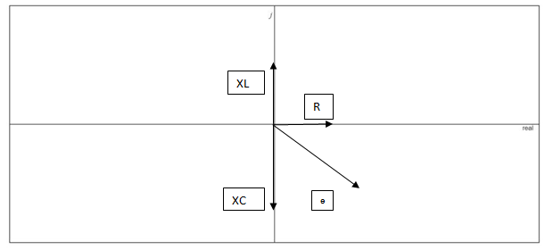
Fig. 15.90
Expert Solution & Answer
Want to see the full answer?
Check out a sample textbook solution
Students have asked these similar questions
Could you use Zeq (impedance to solve)
Match the following:
The technology in which we use mechanical and electrical
equipment to enhance the conversion of solar energy to heat
and electric power.
Choose...
The technology which absorb solar energy, store and distribute
Choose...
it in a natural manner without using mechanical equipment.
3. Find the voltage v for the elements in Fig. 15.122 using
complex algebra. Sketch the waveforms of v and i on the
same set of axes.
1= 2x 10- sin(157t + 40)
S00s pF v
(c)
FIG. 15.122
Problem 3.
Chapter 15 Solutions
Introductory Circuit Analysis (13th Edition)
Ch. 15 - For the resistive element in Fig. 15.81: Write the...Ch. 15 - For the resistive element in Fig. 15.82: Write the...Ch. 15 - For the inductive element of Fig. 15.83: a. Write...Ch. 15 - For the inductive element of Fig. 15.84: Calculate...Ch. 15 - For the inductive element of Fig. 15.85: Write the...Ch. 15 - For the capacitive element of Fig. 15.86: Write...Ch. 15 - For the capacitive element of Fig. 15.87:...Ch. 15 - For the capacitive element of Fig. 15.88: Write...Ch. 15 - Sketch the impedance diagram of a 120 k resistor.Ch. 15 - Sketch the impedance diagram of a 5 mH coil...
Ch. 15 - Sketch the impedance diagram of a 0.02 F capacitor...Ch. 15 - Calculate the total impedance of the circuits in...Ch. 15 - Calculate the total impedance of the circuits in...Ch. 15 - Find the type and impedance in ohms of the series...Ch. 15 - For the circuit in Fig. 15.92 Find the total...Ch. 15 - Repeat problem 15 for the circuit in Fig. 15.93,...Ch. 15 - For the circuit in Fig. 15.94: Find the total...Ch. 15 - Repeat Problem 17 for the circuit in Fig. 15.95...Ch. 15 - For the circuit of Fig. 15.96: Find the total...Ch. 15 - For the circuit of Fig. 15.97: Find the current...Ch. 15 - Prob. 21PCh. 15 - Using the oscilloscope reading in Fig. 15.99,...Ch. 15 - Using the DMM current reading and the oscilloscope...Ch. 15 - Using the oscilloscope reading in Fig. 15.101:...Ch. 15 - An electrical load has a power factor of 0.8...Ch. 15 - Find the series element or elements that must be...Ch. 15 - Calculate the voltages V1andV2 for the circuits in...Ch. 15 - Calculate the voltages V1andV2 for the circuits in...Ch. 15 - For the circuit in Fig. 15.105: Determine...Ch. 15 - For the circuit in Fig. 15.106: a. Plot ZT and T...Ch. 15 - Prob. 31PCh. 15 - For the series R-L-C circuit in Fig. 15.108: Plot...Ch. 15 - For the series R-C circuit in Fig. 15.109:...Ch. 15 - For the circuit in Fig. 15.110, determine the...Ch. 15 - For the oscilloscope traces in Fig. 15.111:...Ch. 15 - For the network in Fig. 15.92 (usef=1kHz):...Ch. 15 - For the network in Fig. 15.93: Plot the impedance...Ch. 15 - For the network in Fig. 15.105: Find the rms...
Additional Engineering Textbook Solutions
Find more solutions based on key concepts
A constant voltage of 10V is applied to a 50H inductance, as shown in Figure P3.51 Figure P3 51 The current in ...
Electrical Engineering: Principles & Applications (7th Edition)
Identify the type of input and output configuration for each diff-amp in Figure 18-35.
Electronics Fundamentals: Circuits, Devices & Applications
Three point charges of equal magnitude q, that will yield a zero net electric field at the origin.
Engineering Electromagnetics
For the “tank” circuit in Fig. 14.79, find the resonant frequency.
Figure 14.79
For Probs. 14.39, 14.71, and 1...
Fundamentals of Electric Circuits
The current source in the circuit shown generates the current pulse
Find (a) v (0); (b) the instant of time gr...
Electric Circuits. (11th Edition)
Electric power systems provide energy in a variety of commercial and industrial settings. Make a list of system...
Principles and Applications of Electrical Engineering
Knowledge Booster


Learn more about
Need a deep-dive on the concept behind this application? Look no further. Learn more about this topic, electrical-engineering and related others by exploring similar questions and additional content below.Similar questions
- Quèstion 17 Giving the following tank circuit, if L= 50 mH, R=102 and C=5µF. The approximate value of w, is L. C 1989.97 None of the answers 314.7 1150.36arrow_forwardPractice Exercise 1.1 Answer the following accordingly: 1. (3-j4) + (10244) then convert to rectangular form 2. (22000+j13)/(32-17) then convert to rectangular form 3. Convert 95-j12 to polar formarrow_forward20. For the circuit of Fig. 15.97: a. Find the current I. b. Find the voltage Vc. E = 48V 0° Xc R 80 160 + Vc- XL, 20 Ω E2 = 32 V L45° ll IL 14 0 FIG. 15.97 +arrow_forward
- 16. Determine the following from the given R-L-C series circuit: i) Impedance Z ii) Current i iii) Voltage across resistance VŔ iv) Voltage across inductance V₁ Pe 70.7 sin af v) Voltage across capacitance Ve vi) Total power delivered vii) Power factor R-30 W X₁ = 701 X₁ = 30 X 000 Karrow_forward(i) A coil of resistance 60Ω and inductance 400mH is connected in parallel with a 15uF capacitor across a 230V 50Hz supply. Sketch the circuit diagram and calculate: The current in the coil The current in the capacitor The supply current and its phase angle The circuit impedance The power consumed The apparent power The reactive power (ii) Sketch the phasor diagram of the circuit, and use complex numbers to verify your answer in parts a to d. (iii) Use multisim or something similar to prove your answers in e. and f. and discuss possible application of the above circuit. Critically analyse the circuit for your chosen application giving recommendations for improvements.arrow_forwardMinistry of Manpower Directorate General of Technological Education Salalah College of Technology Zlectrical Inginearina Problem - 8 Refer to the circuit below and -25V C2 N. compute the following: i) Total capacitance ii) Voltage across C, iii)Charge across C, iv)Voltage across C5 5 uF C1 5 uF 5 uF C4 5 uF C6 5 uF -16-65V. C5 5 uF (Take V, as 25V) 8-35V VT 25Varrow_forward
- termining the impedance and current of the system, the voltage across the resistor, and the voltage across the inductor. Could you please forward the response as a print of a handwritten answer? I got these two answers earlier. Which of them would be correct Impedance Z= (1000 + j 90.836) ohm Current I= 0.219∠-5.19° A Voltage across resistor VR = 219.097∠-5.19° V Voltage across inductor VL = 165.195∠84.81° V Impedance will be Z= 1004.052 ∠ 5.12° Current will be i = 0.221 ∠ -5.19° A. Volatge across resistor will be VR = 211.9∠ -5.19° V Volatge across inductor will be VL = 165.12 ∠ 84.81°Varrow_forwardFundamentals of Electrical Engineering 2020/2021 Dr. Yaseen H. Tahir xample: (example 15-3, page 388, David) (H. W.) A 1 MF capacitance is to be constructed from rolled-up sheets of aluminum foil separated by a layer of paper 0.1 mm thick. Calculate the required area for each sheet of foil if the relative permittivity of the paper is 6. Jution:arrow_forwardThe voltage and current of an element are i(t) = 3.cos(1000t + 10°) V(t) = 6.cos(1000t – 80°) The element is Select one: a. resistor and capacitor (R and C) b. Сарacitor C c. resistor R d. Inductor Larrow_forward
- Solve the following for ALL circuits. Show the summary of your answers at the end of each problem. All answers should be in polar form! a. Total Current b. Individual Currents c. Individual Voltages d. True/Real power e. Reactive power f. Apparent power 1. Circuit 1 (freq=200 Hz) 10 K www 10 COSwt 100 100 LA HE 10 pFarrow_forward16. Determine the following from the given R-L-C series circuit: i) Impedance Z ii) Current i iii) Voltage across resistance V iv) Voltage across inductance V₁ v) Voltage across capacitance Ve vi) Total power delivered vii) Power factor 70.7 sheet Ⓒ 40 R = 30 X₁70 X 30 www vooarrow_forward3. Find the voltage v for the elements in Fig. 15.122 using complex algebra. Sketch the waveforms of u and i on the same set of axes. FIG. 15.122 Problem 3. i= 2 x 10 sin(157r+40") 50.05 µFUarrow_forward
arrow_back_ios
SEE MORE QUESTIONS
arrow_forward_ios
Recommended textbooks for you
 Introductory Circuit Analysis (13th Edition)Electrical EngineeringISBN:9780133923605Author:Robert L. BoylestadPublisher:PEARSON
 Delmar's Standard Textbook Of ElectricityElectrical EngineeringISBN:9781337900348Author:Stephen L. HermanPublisher:Cengage Learning
 Programmable Logic ControllersElectrical EngineeringISBN:9780073373843Author:Frank D. PetruzellaPublisher:McGraw-Hill Education
 Fundamentals of Electric CircuitsElectrical EngineeringISBN:9780078028229Author:Charles K Alexander, Matthew SadikuPublisher:McGraw-Hill Education
 Electric Circuits. (11th Edition)Electrical EngineeringISBN:9780134746968Author:James W. Nilsson, Susan RiedelPublisher:PEARSON
 Engineering ElectromagneticsElectrical EngineeringISBN:9780078028151Author:Hayt, William H. (william Hart), Jr, BUCK, John A.Publisher:Mcgraw-hill Education,
Introductory Circuit Analysis (13th Edition)
Electrical Engineering
ISBN:9780133923605
Author:Robert L. Boylestad
Publisher:PEARSON
Delmar's Standard Textbook Of Electricity
Electrical Engineering
ISBN:9781337900348
Author:Stephen L. Herman
Publisher:Cengage Learning
Programmable Logic Controllers
Electrical Engineering
ISBN:9780073373843
Author:Frank D. Petruzella
Publisher:McGraw-Hill Education
Fundamentals of Electric Circuits
Electrical Engineering
ISBN:9780078028229
Author:Charles K Alexander, Matthew Sadiku
Publisher:McGraw-Hill Education
Electric Circuits. (11th Edition)
Electrical Engineering
ISBN:9780134746968
Author:James W. Nilsson, Susan Riedel
Publisher:PEARSON
Engineering Electromagnetics
Electrical Engineering
ISBN:9780078028151
Author:Hayt, William H. (william Hart), Jr, BUCK, John A.
Publisher:Mcgraw-hill Education,
What Is a Plane Wave? — Lesson 2; Author: EMViso;https://www.youtube.com/watch?v=ES2WFevGM0g;License: Standard Youtube License