
Videos
For the inductive element of Fig. 15.83:
a. Write the current in phasor form.
b. Calculate the voltage across the inductor in phasor form.
c. Sketch the phasor diagram of the voltage and current.
d. Write the voltage in the sinusoidal format.
e. Sketch the waveform of the voltage and current.
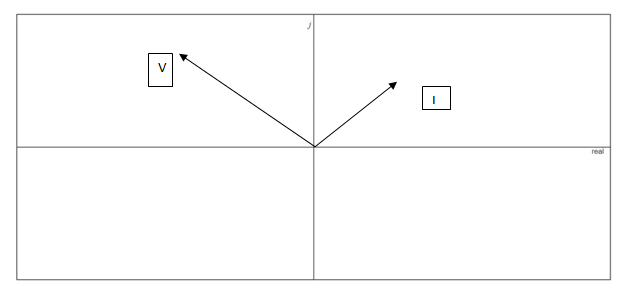
Fig. 15.83
Want to see the full answer?
Check out a sample textbook solution
Chapter 15 Solutions
Introductory Circuit Analysis (13th Edition)
Additional Engineering Textbook Solutions
Programmable Logic Controllers
Electric Circuits. (11th Edition)
Electric Circuits (10th Edition)
Principles and Applications of Electrical Engineering
ANALYSIS+DESIGN OF LINEAR CIRCUITS(LL)
Microelectronics: Circuit Analysis and Design


- Eхample: Convert the following quantities into rectangular form. a) 12/30° b) 270/1.7n c) 40 /105° Solution:arrow_forwardQUESTION 3 An inductor, a capacitor, and a resistor are connected in parallel with a function generator. The inductor draws 100mA RMS, the capacitor draws 150mA RMS, and the resistor draws 200mA RMS. Find the magnitude of the total current. O 450mA RMS O 544mA RMS O 352mA RMS O 206mA RMSarrow_forwardI) Convert the following phasors to the time domain if the frequency is I KHz. . h-3 A a) k- 12 /40 b)arrow_forward
- Impedance of AC circuit and Admittance of AC circuitSHOW THE CIRCUIT USING ANY SOFTWARE OR YOU CAN DRAW IT MANUAALYY thNAKSSarrow_forwardA resistor is in series with a capacitor connected 120V/60Hz generator. Given R=22kohms, C=150nF. a. Find Xc, Vr, Vc, & I b. find Z in polar formarrow_forwarda) Determine the resistance and series inductance or capacitance for each of the following impedances, assuing a frequency of 50HZ i. (4.0+ j7.0)z CR (4) 154-60°zarrow_forward
- Find the following: a. Find the total admittance Yr in polar form. b. Draw the impedence diagram. c. Find Is, IR, and L in phasor form. d. Verify Kirchhoff's current law at node 1. e. Find the sinusoidal expressions for the currents and voltage if the frequency is 60 Hz. I YT E = 60 VZ 0° ( 12 2 XL 10 2 llarrow_forward1. Consider the two circuits below being driven by an AC source Vac. What is the impedance between terminals a and b as the frequency goes to zero? What is the impedance as the frequency become extremely high? ell L1 1 ΜΗ C1 1 µF C2 1 µF b t Vac sine L2 1 ΜΗ C3 1 µF L3 1 µH Vac sinearrow_forwardAn rms voltage of 22.2 V with a frequencyof 1.00 kHz is applied to a 0.290-mH inductor. (a) What is the rmscurrent in this circuit? (b) By what factor does the current changeif the frequency of the voltage is doubled? (c) Calculate the current for a frequency of 2.00 kHzarrow_forward
- 58. Two capacitors, a 20 µF and a 30 µF, are connected in series to a 60-Hz source. What is the total capacitive reactance? a. 117.96 N b. 221.04 N c. 253.05 N d. 333.16 Narrow_forwardPure inductive load has power factor equal Select one: -1 0 0.8 1arrow_forwardProblem 5 Find the equivalent inductance Leg for the network shown below. 72 mH oooo Leg 49 mH elle elle 313 mH elle 64 mH elle 80 mHarrow_forward
 Power System Analysis and Design (MindTap Course ...Electrical EngineeringISBN:9781305632134Author:J. Duncan Glover, Thomas Overbye, Mulukutla S. SarmaPublisher:Cengage Learning