
Introductory Circuit Analysis (13th Edition)
13th Edition
ISBN: 9780133923605
Author: Robert L. Boylestad
Publisher: PEARSON
expand_more
expand_more
format_list_bulleted
Videos
Textbook Question
Chapter 15, Problem 14P
Find the type and impedance in ohms of the series circuit elements that must be in the closed container in Fig. 15.91 for the indicated voltages and currents to exist at the input terminals. (Find the simplest series circuit that will satisfy the indicated conditions.)
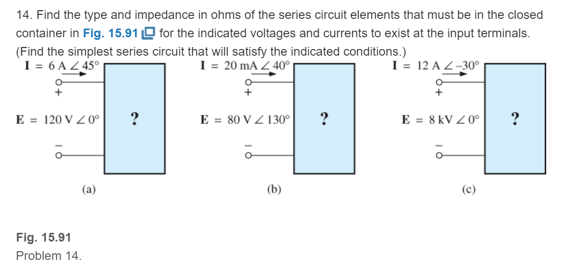
Fig. 15.91
Expert Solution & Answer
Want to see the full answer?
Check out a sample textbook solution
Students have asked these similar questions
Problem 1
The Buck converter below delivers power to a voltage source through an inductor La = 0.2 mH.
Assume the average output current I₁ = 5 A. Switching frequency f. = 50 kHz. D = 0.8
(a) Assume the output voltage, Vo, equals 200V. Calculate the input voltage, Va.
(b) Find the ripple of the output current.
(c) Calculate the maximum and the minimum value of the inductor current
(d) Sketch the output current, i(t), and the de current, i(t).
(e) The load on the output is reduced. Assume the output voltage is still 200 V. Calculate I. when
the converter is on the boundary between continuous and discontinuous mode.
ia
+ Va
+
Voi
La
Fig. 1
Vo-V₂
+
R-5.6ka
* Asiacell I.
docs.google.com a
Jadi smie.2013106633@muc.edu.iq si cudi
الحساب
مطلوب
\Q.4
ارجو كتابة النتائج فقط بشكل مختصر
The circuit shown Figure has a current of 2.5 mA. Find the following
R- 3.3 ka
quantities:
a. The total resistance of the circuit.
b. The value of the unknown resistance, R2.
c. The voltage drop across each resistor in the circuit.
d. The power dissipated by each resistor in the circuit.
E-45 V
!- 2.5 mA
إجابتك
إرسال
رجوع
عدم إرسال كلمات المرور عبر نماذج Google مطلقًا.
jE ESLYI AI-Mansour University College Jalstiaill lis cLail
إساءة الاستخدام
Googlez ilai
->
120 VRMS
1
Select one:
OA. 360 VRMS
OB. 40 VRMS
OC. 80 VRMS
OD. 240 VRMS
لشما
What is the secondary voltage if the
turns ratio is 1:3?
Chapter 15 Solutions
Introductory Circuit Analysis (13th Edition)
Ch. 15 - For the resistive element in Fig. 15.81: Write the...Ch. 15 - For the resistive element in Fig. 15.82: Write the...Ch. 15 - For the inductive element of Fig. 15.83: a. Write...Ch. 15 - For the inductive element of Fig. 15.84: Calculate...Ch. 15 - For the inductive element of Fig. 15.85: Write the...Ch. 15 - For the capacitive element of Fig. 15.86: Write...Ch. 15 - For the capacitive element of Fig. 15.87:...Ch. 15 - For the capacitive element of Fig. 15.88: Write...Ch. 15 - Sketch the impedance diagram of a 120 k resistor.Ch. 15 - Sketch the impedance diagram of a 5 mH coil...
Ch. 15 - Sketch the impedance diagram of a 0.02 F capacitor...Ch. 15 - Calculate the total impedance of the circuits in...Ch. 15 - Calculate the total impedance of the circuits in...Ch. 15 - Find the type and impedance in ohms of the series...Ch. 15 - For the circuit in Fig. 15.92 Find the total...Ch. 15 - Repeat problem 15 for the circuit in Fig. 15.93,...Ch. 15 - For the circuit in Fig. 15.94: Find the total...Ch. 15 - Repeat Problem 17 for the circuit in Fig. 15.95...Ch. 15 - For the circuit of Fig. 15.96: Find the total...Ch. 15 - For the circuit of Fig. 15.97: Find the current...Ch. 15 - Prob. 21PCh. 15 - Using the oscilloscope reading in Fig. 15.99,...Ch. 15 - Using the DMM current reading and the oscilloscope...Ch. 15 - Using the oscilloscope reading in Fig. 15.101:...Ch. 15 - An electrical load has a power factor of 0.8...Ch. 15 - Find the series element or elements that must be...Ch. 15 - Calculate the voltages V1andV2 for the circuits in...Ch. 15 - Calculate the voltages V1andV2 for the circuits in...Ch. 15 - For the circuit in Fig. 15.105: Determine...Ch. 15 - For the circuit in Fig. 15.106: a. Plot ZT and T...Ch. 15 - Prob. 31PCh. 15 - For the series R-L-C circuit in Fig. 15.108: Plot...Ch. 15 - For the series R-C circuit in Fig. 15.109:...Ch. 15 - For the circuit in Fig. 15.110, determine the...Ch. 15 - For the oscilloscope traces in Fig. 15.111:...Ch. 15 - For the network in Fig. 15.92 (usef=1kHz):...Ch. 15 - For the network in Fig. 15.93: Plot the impedance...Ch. 15 - For the network in Fig. 15.105: Find the rms...
Knowledge Booster


Learn more about
Need a deep-dive on the concept behind this application? Look no further. Learn more about this topic, electrical-engineering and related others by exploring similar questions and additional content below.Similar questions
- In an autotransformer if the power transferred inductively is equal to the power conducted through, then transformation ratio is given by * 1-0.5 2- 1 3- 2 4- 1.5arrow_forwardFor the following circuit if the secondary voltage of the transformer is 20V rms, the output voltage and the PIV of the diodes are V. 2 Vm C3 D, D2 D3 A D4 C2 C4 + 2Vm 2Vm O 130.1 V, 55 V O 113.1 V, 56.56 V 123.2, 61.61 V 55.5 V, 33 Varrow_forwardplease solve queeeestion 13arrow_forward
- M O E A IV,oK/s 3.lzain IQ öslg äbäi In the breakdown region, a -2 zener didoe behaves like a source c. constant resistance b. constant current a. constant voltage d. none of the above O نقطة واحدة The quiescent point (Q--5 point) is defined by a ac and dc network O None of the above dc network ac network O نقطة واحدة The reverse current in a -4 diode is of the order of |l>arrow_forwardIf vt = 230cis40degrees. determine the equivalent impedance.arrow_forwardDetermine R, so that it absorbs m.p.tarrow_forward
- kindly do this problemarrow_forwardfor the circuit shown below If v_in=5 sin2m10t then corner frequency will be ......Hz 1 UF 2 k Ohm 1 k Ohim 050 060 070 080 vinarrow_forwardFor the following circuit if the secondary voltage of the transformer is 20V rms, the PIV of the diodes are ZV +1H +1 C3 D₂ D₁ 000 000000000 + C₁ O 55 V O 61.61 V 33 V O56.56 V C₂ HE 2V + m D3 + Ca H 2Varrow_forward
arrow_back_ios
SEE MORE QUESTIONS
arrow_forward_ios
Recommended textbooks for you
 Power System Analysis and Design (MindTap Course ...Electrical EngineeringISBN:9781305632134Author:J. Duncan Glover, Thomas Overbye, Mulukutla S. SarmaPublisher:Cengage Learning
Power System Analysis and Design (MindTap Course ...
Electrical Engineering
ISBN:9781305632134
Author:J. Duncan Glover, Thomas Overbye, Mulukutla S. Sarma
Publisher:Cengage Learning
Resonance Circuits: LC Inductor-Capacitor Resonating Circuits; Author: Physics Videos by Eugene Khutoryansky;https://www.youtube.com/watch?v=Mq-PF1vo9QA;License: Standard YouTube License, CC-BY