
Introductory Circuit Analysis (13th Edition)
13th Edition
ISBN: 9780133923605
Author: Robert L. Boylestad
Publisher: PEARSON
expand_more
expand_more
format_list_bulleted
Concept explainers
Videos
Textbook Question
Chapter 15, Problem 12P
Calculate the total impedance of the circuits in Fig. 15.89. Express your answer in rectangular and polar forms and draw the impedance diagram.
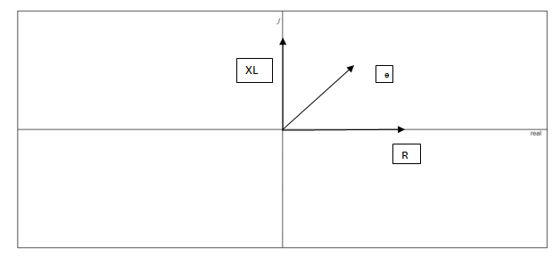
Fig. 18.89
Expert Solution & Answer

Trending nowThis is a popular solution!

Students have asked these similar questions
Quèstion 17
Giving the following tank circuit, if L= 50 mH, R=102 and C=5µF. The approximate
value of w, is
L.
C
1989.97
None of the answers
314.7
1150.36
41. For the network of Fig. 15.148:
a. Calculate E, IR, and Iz in phasor form.
b. Calculate the total power factor, and indicate whether
it is leading or lagging.
c. Calculate the average power delivered to the circuit.
d. Draw the admittance diagram.
e. Draw the phasor diagram of the currents I,, Ig, and Iz,
and the voltage E.
f. Find the current Ic for each capacitor using only
Kirchhoff's current law.
g. Find the series circuit of one resistive and reactive
element that will have the same impedance as the
original circuit.
i, = V2 sin 2x 1000t
220 N
L = 10 mH
R
`1 µF
1 µF
ll
3. Find the voltage v for the elements in Fig. 15.122 using
complex algebra. Sketch the waveforms of v and i on the
same set of axes.
1= 2x 10- sin(157t + 40)
S00s pF v
(c)
FIG. 15.122
Problem 3.
Chapter 15 Solutions
Introductory Circuit Analysis (13th Edition)
Ch. 15 - For the resistive element in Fig. 15.81: Write the...Ch. 15 - For the resistive element in Fig. 15.82: Write the...Ch. 15 - For the inductive element of Fig. 15.83: a. Write...Ch. 15 - For the inductive element of Fig. 15.84: Calculate...Ch. 15 - For the inductive element of Fig. 15.85: Write the...Ch. 15 - For the capacitive element of Fig. 15.86: Write...Ch. 15 - For the capacitive element of Fig. 15.87:...Ch. 15 - For the capacitive element of Fig. 15.88: Write...Ch. 15 - Sketch the impedance diagram of a 120 k resistor.Ch. 15 - Sketch the impedance diagram of a 5 mH coil...
Ch. 15 - Sketch the impedance diagram of a 0.02 F capacitor...Ch. 15 - Calculate the total impedance of the circuits in...Ch. 15 - Calculate the total impedance of the circuits in...Ch. 15 - Find the type and impedance in ohms of the series...Ch. 15 - For the circuit in Fig. 15.92 Find the total...Ch. 15 - Repeat problem 15 for the circuit in Fig. 15.93,...Ch. 15 - For the circuit in Fig. 15.94: Find the total...Ch. 15 - Repeat Problem 17 for the circuit in Fig. 15.95...Ch. 15 - For the circuit of Fig. 15.96: Find the total...Ch. 15 - For the circuit of Fig. 15.97: Find the current...Ch. 15 - Prob. 21PCh. 15 - Using the oscilloscope reading in Fig. 15.99,...Ch. 15 - Using the DMM current reading and the oscilloscope...Ch. 15 - Using the oscilloscope reading in Fig. 15.101:...Ch. 15 - An electrical load has a power factor of 0.8...Ch. 15 - Find the series element or elements that must be...Ch. 15 - Calculate the voltages V1andV2 for the circuits in...Ch. 15 - Calculate the voltages V1andV2 for the circuits in...Ch. 15 - For the circuit in Fig. 15.105: Determine...Ch. 15 - For the circuit in Fig. 15.106: a. Plot ZT and T...Ch. 15 - Prob. 31PCh. 15 - For the series R-L-C circuit in Fig. 15.108: Plot...Ch. 15 - For the series R-C circuit in Fig. 15.109:...Ch. 15 - For the circuit in Fig. 15.110, determine the...Ch. 15 - For the oscilloscope traces in Fig. 15.111:...Ch. 15 - For the network in Fig. 15.92 (usef=1kHz):...Ch. 15 - For the network in Fig. 15.93: Plot the impedance...Ch. 15 - For the network in Fig. 15.105: Find the rms...
Additional Engineering Textbook Solutions
Find more solutions based on key concepts
Explain the main function of each of the following major components of a PLC: a. Processor module (CPU) b. I/O ...
Programmable Logic Controllers
Find I0 and I1 in the circuit in Fig.P2.12.
Basic Engineering Circuit Analysis
Does the severity of an electric shock increase ordecrease with eh of the following changes? a. A decrease in t...
Electric Motors and Control Systems
Design an ideal inverting op-amp circuit such that the voltage gain is Av=25 . The maximum current in any resis...
Microelectronics: Circuit Analysis and Design
Three point charges of equal magnitude q, that will yield a zero net electric field at the origin.
Engineering Electromagnetics
With respect to the circuit in Fig. 5.90, (a) employ Thévenin’s theorem to determine the equivalent network see...
Loose Leaf for Engineering Circuit Analysis Format: Loose-leaf
Knowledge Booster


Learn more about
Need a deep-dive on the concept behind this application? Look no further. Learn more about this topic, electrical-engineering and related others by exploring similar questions and additional content below.Similar questions
- ll 41. For the network of Fig. 15.148: a. Calculate E, IR. and I, in phasor form. b. Calculate the total power factor. and indicate whether it is leading or lagging. c. Calculate the average power delivered to the circuit. d. Draw the admittance diagram. e. Draw the phasor diagram of the currents I,, Ig, and I. and the voltage E. f. Find the current Ic for each capacitor using only Kirchhoff s current law. g. Find the series circuit of one resistive and reactive element that will have the same impedance as the original circuit. 1, = V2 sin 2x 1000r R C. 1 uFarrow_forward41. For the network of Fig. 15.148: a. Calculate E, Ig, and Iz in phasor form. b. Calculate the total power factor, and indicate whether it is leading or lagging. c. Calculate the average power delivered to the circuit. d. Draw the admittance diagram. e. Draw the phasor diagram of the currents I,, IR, and IL. and the voltage E. f. Find the curent Ic for each capacitor using only Kirchhoff's current law. g. Find the series circuit of one resistive and reactive element that will have the same impedance as the original circuit. i, = V2 sin 27 1000t 220 N L = 10 mH R. µF 1 µFarrow_forwardCould you use Zeq (impedance to solve)arrow_forward
- Question 13 Giving the following tank circuit, if L= 50 mH, R=102 and C=5µF. The approximate value of w, is 1989.97 None of the answers 314.7 1150.36arrow_forwardIn the AC network below, determine: R1 5ΚΩ V1 + 120Vrms 1000Hz 0° C1 HE 10μF b. The impedance of the capacitor. a. The angular frequency in the network. c. The impedance of the inductor. d. The voltage at node A. A L1 500mH ww R2 10kQarrow_forward16. Determine the following from the given R-L-C series circuit: i) Impedance Z ii) Current i iii) Voltage across resistance VŔ iv) Voltage across inductance V₁ Pe 70.7 sin af v) Voltage across capacitance Ve vi) Total power delivered vii) Power factor R-30 W X₁ = 701 X₁ = 30 X 000 Karrow_forward
- 1) Calculate: a) the reactance of the inductor, XL,b) the reactance of the capacitor, XC,c) the impedance of the circuit, Z,arrow_forwardThe voltage and current of an element are i(t) = 3.cos(1000t + 10°) V(t) = 6.cos(1000t – 80°) The element is Select one: a. resistor and capacitor (R and C) b. Сарacitor C c. resistor R d. Inductor Larrow_forwardLabel the currents leaving each of the non-reference essential nodes. Use i1, 12, 13 ... 10 VI 1Ω + ΖΩΣV 2Q Μ + 10ΩΣ V Copyright 2015 Pearson Educacion, All Rights Reserved Ο ΖΑarrow_forward
- Problem 1: Obtain the input impedance by replacing the linear transformer by its T equivalent. /100 802 Z 1402 252 m www /30 2002 -160arrow_forward3. Find the voltage v for the elements in Fig. 15.122 using complex algebra. Sketch the waveforms of u and i on the same set of axes. FIG. 15.122 Problem 3. i= 2 x 10 sin(157r+40") 50.05 µFUarrow_forwardSimplify the following expression: Y ABC + ABC +ABC+. + ABCarrow_forward
arrow_back_ios
SEE MORE QUESTIONS
arrow_forward_ios
Recommended textbooks for you
 Introductory Circuit Analysis (13th Edition)Electrical EngineeringISBN:9780133923605Author:Robert L. BoylestadPublisher:PEARSON
 Delmar's Standard Textbook Of ElectricityElectrical EngineeringISBN:9781337900348Author:Stephen L. HermanPublisher:Cengage Learning
 Programmable Logic ControllersElectrical EngineeringISBN:9780073373843Author:Frank D. PetruzellaPublisher:McGraw-Hill Education
 Fundamentals of Electric CircuitsElectrical EngineeringISBN:9780078028229Author:Charles K Alexander, Matthew SadikuPublisher:McGraw-Hill Education
 Electric Circuits. (11th Edition)Electrical EngineeringISBN:9780134746968Author:James W. Nilsson, Susan RiedelPublisher:PEARSON
 Engineering ElectromagneticsElectrical EngineeringISBN:9780078028151Author:Hayt, William H. (william Hart), Jr, BUCK, John A.Publisher:Mcgraw-hill Education,
Introductory Circuit Analysis (13th Edition)
Electrical Engineering
ISBN:9780133923605
Author:Robert L. Boylestad
Publisher:PEARSON
Delmar's Standard Textbook Of Electricity
Electrical Engineering
ISBN:9781337900348
Author:Stephen L. Herman
Publisher:Cengage Learning
Programmable Logic Controllers
Electrical Engineering
ISBN:9780073373843
Author:Frank D. Petruzella
Publisher:McGraw-Hill Education
Fundamentals of Electric Circuits
Electrical Engineering
ISBN:9780078028229
Author:Charles K Alexander, Matthew Sadiku
Publisher:McGraw-Hill Education
Electric Circuits. (11th Edition)
Electrical Engineering
ISBN:9780134746968
Author:James W. Nilsson, Susan Riedel
Publisher:PEARSON
Engineering Electromagnetics
Electrical Engineering
ISBN:9780078028151
Author:Hayt, William H. (william Hart), Jr, BUCK, John A.
Publisher:Mcgraw-hill Education,
How do Electric Transmission Lines Work?; Author: Practical Engineering;https://www.youtube.com/watch?v=qjY31x0m3d8;License: Standard Youtube License