
Delmar's Standard Textbook Of Electricity
7th Edition
ISBN: 9781337900348
Author: Stephen L. Herman
Publisher: Cengage Learning
expand_more
expand_more
format_list_bulleted
Question
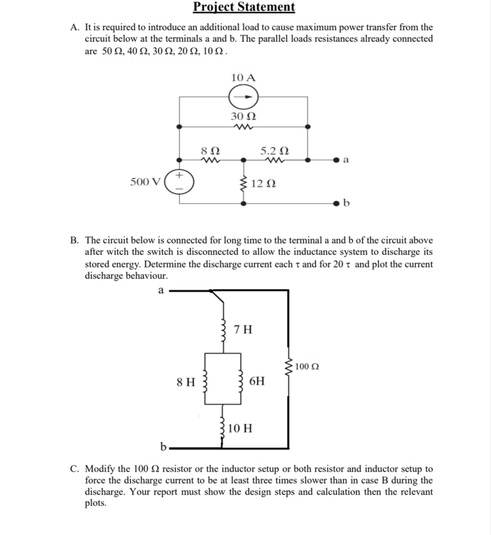

Transcribed Image Text:Project Statement
A. It is required to introduce an additional load to cause maximum power transfer from the
circuit below at the terminals a and b. The parallel loads resistances already connected
are 50 Ω, 40 Ω, 30 Ω, 20 Ω, 10 Ω.
10 A
30022
w
8 Ω
5.2 Ω
w
w
a
+
500 V
12 Ω
B. The circuit below is connected for long time to the terminal a and b of the circuit above
after witch the switch is disconnected to allow the inductance system to discharge its
stored energy. Determine the discharge current each τ and for 20 t and plot the current
discharge behaviour.
a
7 H
100 Ω
8 H
6H
10 H
b
C. Modify the 100 2 resistor or the inductor setup or both resistor and inductor setup to
force the discharge current to be at least three times slower than in case B during the
discharge. Your report must show the design steps and calculation then the relevant
plots.
Expert Solution
This question has been solved!
Explore an expertly crafted, step-by-step solution for a thorough understanding of key concepts.

Step by stepSolved in 2 steps with 7 images

Knowledge Booster

Similar questions
- Remaining Time: 56 minutes, 12 seconds. - Question Completion Status: Rs 120 0 Vs RL 20 V B The source in Figure 2 has an internal resistance of 120 Ohm. Determine the load power for each of the following values of the variable load resistance (a) 02 O a. 330 m O b. 450 mW O c. 500 mW O d.0 mW Click Save amd Submit to save and submit. Click Save All Answers to save all ansuers. Save All Answe „.Electronics Funda Take Test: 29°C ablo claw acer F10 F11 F12 F8 F9 F5 F6 F7 NumLk Sar Lk F3 F4 国 *arrow_forwardShow me how to approach this problem with steps pleasearrow_forwardApplying star delta conversions:Determine the value of the total resistanceApply a voltage of 12 volts to the circuitDetermine the total current.Determine Voltage Across R14arrow_forward
- Q5arrow_forwardFor a certain power shpply, the no load and full load voltage are 22 V and 18 V respectively. What will be the load regulation?arrow_forwardFor the given circuit in figure, data is mentioned. Find the fault current when the system is unloaded when the fault occurs at terminal P.arrow_forward
- Q2arrow_forwardWhich statement is correct about a series circuit? The sum of currents in each load multiplied by the total resistance determines t voltage. The sum of the individual resistances equals the total resistance. The sum of all the voltage drops equals the source voltage. The voltage drops are equal to the input source. In a series circuit, the current, I, is Different in each resistor The highest near the positive and negative terminals of the voltage source The same everywhere Different at all points along the circuitarrow_forwardAnswerthe follonwing based on the 3-phase configuratio in figure 7, worksshet4. What is Ammeter A4 is measuring - A- line current, B- Phase current, C- neither "a" nor "b", D- both "a" and "b" Ammeter A5 is measuring - A- line current, B- phase current, C- neither "a" nor "b", D- both "a" and "b". Ammeter A6 is measuring - A line current, B- phase current, C-neither "a" nor "b"., D- both 'A' and "b"arrow_forward
- Consider the RC circuit in Figure 2 below. Assuming the switch has been open for a long time before it is closed, fill in a table providing the current through each component and the voltage across each component immediately after the switch is closed, and a very long time after the switch is closed. Next, figure out the time constant for the circuit. (Hint: Assign currents to each branch. Set up the necessary KVL and KCL equations. Eliminate all but one variable to get an equation for just one of the currents. You shouldn’t have to solve this equation to recognize the time constant!)arrow_forwardCalculate the indicated currents and voltages. R1 R6 4 kN 12 kN R7 R8 R238 kN R4 24 k2 E 72 V 9 kN 3 kN R3 R5 R9 b 12kN 12 k2 6 kN O V7=19.626V, Is=7.344A, 15-2.8A O V7=19.636V, Is=7.364A, 15=3A O V7-19.646V, Is=7.364A, 15=2.7A O V7=19.656V, Is=7.354A, 15-2.9Aarrow_forwardIdentify schematic partsarrow_forward
arrow_back_ios
SEE MORE QUESTIONS
arrow_forward_ios
Recommended textbooks for you
- Delmar's Standard Textbook Of ElectricityElectrical EngineeringISBN:9781337900348Author:Stephen L. HermanPublisher:Cengage Learning
Delmar's Standard Textbook Of Electricity
Electrical Engineering
ISBN:9781337900348
Author:Stephen L. Herman
Publisher:Cengage Learning