
Fundamentals of Electric Circuits
6th Edition
ISBN: 9780078028229
Author: Charles K Alexander, Matthew Sadiku
Publisher: McGraw-Hill Education
expand_more
expand_more
format_list_bulleted
Videos
Textbook Question
Chapter 13.4, Problem 4PP
Find the input impedance of the circuit in Fig. 13.25 and the current from the voltage source.
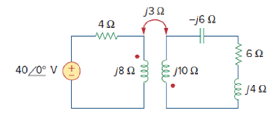
Figure 13.25
For Practice Prob. 13.4.
Answer: 8.58∠58.05° Ω, 4.662∠− 58.05° A.
Expert Solution & Answer
Want to see the full answer?
Check out a sample textbook solution
Students have asked these similar questions
We want to build an impedance matching transformer that matches the output impedance of an amplifier connected to the primary, with a number of turns Np, whose impedance is 600 Ω, with an 8Ω speaker connected to the secondary, with a number of turns Ns. The Np/Ns transformation ratio of the matcher is:
answer:8,66
Given a 115kV/13.2kV distribution transformer rated at 30MVA with an 8% nameplate impedance what is the full Load current in amps
a. A single-phase semi-converter supplies an inductive load having an impedance of 3k. Assume that the output current is constant and is equal to Id. If the supply voltage is 220V and the firing angle is maintained at /2, calculate (i) Average output voltage, (ii) Supply RMS current, (iii) Supply fundamental RMS current.
Chapter 13 Solutions
Fundamentals of Electric Circuits
Ch. 13.2 - Determine the voltage Vo in the circuit of Fig....Ch. 13.2 - Determine the phasor currents I1 and I2 in the...Ch. 13.3 - Prob. 3PPCh. 13.4 - Find the input impedance of the circuit in Fig....Ch. 13.4 - For the linear transformer in Fig. 13.26(a), find...Ch. 13.4 - Solve the problem in Example 13.1 (see Fig. 13.9)...Ch. 13.5 - The primary current to an ideal transformer rated...Ch. 13.5 - In the ideal transformer circuit of Fig. 13.38,...Ch. 13.5 - Find Vo in the circuit of Fig. 13.40. Figure 13.40...Ch. 13.6 - Refer to Fig. 13.43. If the two-winding...
Ch. 13.6 - In the autotransformer circuit of Fig. 13.45, find...Ch. 13.7 - Prob. 12PPCh. 13.8 - Prob. 13PPCh. 13.9 - Refer to Fig. 13.61. Calculate the turns ratio...Ch. 13.9 - Calculate the turns ratio of an ideal transformer...Ch. 13.9 - In Example 13.17, if the eight 100-W bulbs are...Ch. 13 - Refer to the two magnetically coupled coils of...Ch. 13 - Prob. 2RQCh. 13 - Prob. 3RQCh. 13 - Prob. 4RQCh. 13 - The ideal transformer in Fig. 13.70(a) has N2/N1 =...Ch. 13 - Prob. 6RQCh. 13 - A three-winding transformer is connected as...Ch. 13 - Prob. 8RQCh. 13 - Prob. 9RQCh. 13 - Prob. 10RQCh. 13 - For the three coupled coils in Fig. 13.72,...Ch. 13 - Using Fig. 13.73, design a problem to help other...Ch. 13 - Two coils connected in series-aiding fashion have...Ch. 13 - (a) For the coupled coils in Fig. 13.74(a), show...Ch. 13 - Two coils are mutually coupled, with L1 = 50 mH,...Ch. 13 - Given the circuit shown in Fig. 13.75, determine...Ch. 13 - For the circuit in Fig. 13.76, find Vo. Figure...Ch. 13 - Find v(t) for the circuit in Fig. 13.77.Ch. 13 - Prob. 9PCh. 13 - Find vo in the circuit of Fig. 13.79. Figure 13.79...Ch. 13 - Use mesh analysis to find ix in Fig. 13.80, where...Ch. 13 - Determine the equivalent Leq in the circuit of...Ch. 13 - For the circuit in Fig. 13.82, determine the...Ch. 13 - Obtain the Thevenin equivalent circuit for the...Ch. 13 - Find the Norton equivalent for the circuit in Fig....Ch. 13 - Obtain the Norton equivalent at terminals a-b of...Ch. 13 - In the circuit of Fig. 13.86, ZL is a 15-mH...Ch. 13 - Find the Thevenin equivalent to the left of the...Ch. 13 - Determine an equivalent T-section that can be used...Ch. 13 - Determine currents I1, I2, and I3 in the circuit...Ch. 13 - Prob. 21PCh. 13 - Find current Io in the circuit of Fig. 13.91.Ch. 13 - Let is = 5 cos (100t) A. Calculate the voltage...Ch. 13 - In the circuit of Fig. 13.93, (a) find the...Ch. 13 - Prob. 25PCh. 13 - Find Io in the circuit of Fig. 13.95. Switch the...Ch. 13 - Find the average power delivered to the 50-...Ch. 13 - In the circuit of Fig. 13.97, find the value of X...Ch. 13 - Prob. 29PCh. 13 - (a) Find the input impedance of the circuit in...Ch. 13 - Using Fig. 13.100, design a problem to help other...Ch. 13 - Two linear transformers are cascaded as shown in...Ch. 13 - Determine the input impedance of the air-core...Ch. 13 - Using Fig. 13.103, design a problem to help other...Ch. 13 - Find currents I1, I2, and I3 in the circuit of...Ch. 13 - As done in Fig. 13.33, obtain the relationships...Ch. 13 - A 2402,400-V rms step-up ideal transformer...Ch. 13 - Design a problem to help other students better...Ch. 13 - A 1,200240-V rms transformer has impedance on the...Ch. 13 - The primary of an ideal transformer with a turns...Ch. 13 - Given I2 = 2 A, determine the value of Is in Fig....Ch. 13 - For the circuit in Fig. 13.107, determine the...Ch. 13 - Obtain V1 and V2 in the ideal transformer circuit...Ch. 13 - In the ideal transformer circuit of Fig. 13.109,...Ch. 13 - For the circuit in Fig. 13.110, find the value of...Ch. 13 - (a) Find I1 and I2 in the circuit of Fig. 13.111...Ch. 13 - Prob. 47PCh. 13 - Using Fig. 13.113, design a problem to help other...Ch. 13 - Find current ix in the ideal transformer circuit...Ch. 13 - Prob. 50PCh. 13 - Use the concept of reflected impedance to find the...Ch. 13 - For the circuit in Fig. 13.117, determine the...Ch. 13 - Refer to the network in Fig. 13.118. (a) Find n...Ch. 13 - A transformer is used to match an amplifier with...Ch. 13 - For the circuit in Fig. 13.120, calculate the...Ch. 13 - Find the power absorbed by the 100- resistor in...Ch. 13 - For the ideal transformer circuit of Fig. 13.122...Ch. 13 - Determine the average power absorbed by each...Ch. 13 - In the circuit of Fig. 13.124, let vs = 165...Ch. 13 - Refer to the circuit in Fig. 13.125 on the...Ch. 13 - For the circuit in Fig. 13.126, find Il, I2, and...Ch. 13 - For the network in Fig. 13.127, find: (a) the...Ch. 13 - Find the mesh currents in th circuit of Fig....Ch. 13 - For the circuit in Fig. 13.129. find the turns...Ch. 13 - Calculate the average power dissipated by the 20-...Ch. 13 - Design a problem to help other students better...Ch. 13 - An autotransformer with a 40 percent tap is...Ch. 13 - In the ideal autotransformer of Fig. 13.131,...Ch. 13 - In the circuit of Fig. 13.131, N1 = 190 turns and...Ch. 13 - In the ideal transformer circuit shown in Fig....Ch. 13 - When individuals travel, their electrical...Ch. 13 - In order to meet an emergency, three single-phase...Ch. 13 - Figure 13.135 on the next page shows a three-phase...Ch. 13 - Consider the three-phase transformer shown in Fig....Ch. 13 - A balanced three-phase transformer bank with the...Ch. 13 - Using Fig. 13.138, design a problem to help other...Ch. 13 - The three-phase system of a town distributes power...Ch. 13 - Use PSpice or MultiSim to determine the mesh...Ch. 13 - Use PSpice or MultiSim to find I1, I2, and I3 in...Ch. 13 - Prob. 80PCh. 13 - Use PSpice or MultiSim to find I1, I2, and I3 in...Ch. 13 - A stereo amplifier circuit with ail output...Ch. 13 - A transformer having 2,400 turns on the primary...Ch. 13 - A radio receiver has an input resistance of 300 ....Ch. 13 - A step-down power transformer with a turns ratio...Ch. 13 - A 240120-V rms power transformer is rated at 10...Ch. 13 - A 4-kVA, 2,400240-V rms transformer has 250 turns...Ch. 13 - A 25,000240-V rms distribution transformer has a...Ch. 13 - A 4,800-V rms transmission line feeds a...Ch. 13 - A four-winding transformer (Fig. 13.146) is often...Ch. 13 - A 440/110-V ideal transformer can be connected to...Ch. 13 - Ten bulbs in parallel are supplied by a 7,200120-V...
Knowledge Booster


Learn more about
Need a deep-dive on the concept behind this application? Look no further. Learn more about this topic, electrical-engineering and related others by exploring similar questions and additional content below.Similar questions
- A coil of inductance 318.3 mH and neg[1]ligible resistance is connected in series with a 200 resistor to a 240V, 50 Hz supply. Calculate (a) the inductive reactance of the coil, (b) the impedance of the circuit, (c) the current in the circuit, (d) the p.d. across each component, and (e) the circuit phase anglearrow_forwardCalculate the mesh currents in the circuit of Fig. 13.11.arrow_forwardThe diagram shown below is a typical tuning circuit. Considering this circuit comprises a transformer (with a coil ratio of 20:1 and an HV side voltage of 240V ), a capacitor of impedance -j20Ω, an inductor of impedance j40Ω, and a 50Ω resistor, determine: the current supplied by the source (0.2228) the impedance seen at the supply (HV side)(21540.55) the power dissipated by the resistor(2.482 watts) the operating power factor of the fitting(0.928 lagging) If the capacitor is now removed from the above circuit and is placed in parallel with the secondary of the transformer, redraw the circuit diagram and recalculate parts a. to d. in question (i). Draw the phasor diagram for both series and parallel RLC circuits in parts (i) and (ii). Discuss the effects of changing the capacitor connection in parallel on the power factor of the circuit. State the benefits of using the transformer in the above circuit. Explain the operating principle of the transformer with particular reference to…arrow_forward
- single coil 600 turns instrument transformer, operating in the step-down mode with a 40 percent tap, supplies a 5 kVA, 0.88 power factor inductive load. The input to the transformer is 3.3 kV, 50 Hz. Assume that leakage effects and minor losses in transformer are negligible. Determine the following : (0) Turn ratio; (ii) Load current(in Amp); (iii) Incoming line current(in Amp); (iv) Transformed current (in Amp); (v) Apparent power conducted(in kVA)and (vi) Apparent power transformed"arrow_forwardA 5,000-kVA, 3-phase transformer, 13.2/33-kV, A/Y, has a copper loss of 11 kW. The impedance drop at full-load is 7.5%. Calculate the primary voltage when a load of 4000 kW at 0.8 p.f. is delivered at 33 kv.arrow_forwardCalculate the equivalent impedance of a circuit in which a coil of wire having a value of 5∠53.2ºohm is connected in parallel with a capacitive reactance of 6.25 ohms.arrow_forward
- A 2,400/480-V rms step-down ideal transformer delivers 50 kW to a resistive load. Calculate:(a) the turns ratio(b) the primary current(c) the secondary currentarrow_forwardA coil of inductance 318.3 mH and negligible resistance is connected in series with a 200 resistor to a 240V, 50 Hz supply. Calculate (a) the inductive reactance of the coil, (b) the impedance of the circuit, (c) the current in the circuit, (d) the p.d. across each component, and (e) the circuit phase anglearrow_forwardA transformer has 440 primary windings and 22 secondary windings. The potential difference across the primary coil is 100 V. The secondary coil is connected across a 125-ohm resistor. Find (a) secondary current (b) primary current. Hint: Use conservation of power. (c) effective load resistance of the SECONDARY COIL, which is connected across a 125 ohm resistor.arrow_forward
- The impedance value for a network containing the utility and a transformer is Select one: None of these Zt=√(〖((Ztranformer)〗2+〖((Zutility)〗2 Zt=Ztransformer+Zutility Zt=√(〖((Xtranformer+Xutility)〗2+〖((Rtranformer+Rutility)〗2arrow_forwardA resistor of 6 ohms and an unknown impedance coil in series draws 12 A from a 120 V, 60 Hz line. If the real power taken from the line is 1152 Watts, what is the coil inductance?arrow_forwardAn industrial plant is powered with a delta delta system, along with a transformer bank made up of single-phase transformers of 20KVA, 2300/230 V each. The bank supplies a 40 KVA load with a power factor of 0.7 (-). If a damaged transformer is removed for repair, calculate:a) The load in KVA that each transformer has.b) The nominal load of the transformer bank W.arrow_forward
arrow_back_ios
SEE MORE QUESTIONS
arrow_forward_ios
Recommended textbooks for you
 Introductory Circuit Analysis (13th Edition)Electrical EngineeringISBN:9780133923605Author:Robert L. BoylestadPublisher:PEARSON
 Delmar's Standard Textbook Of ElectricityElectrical EngineeringISBN:9781337900348Author:Stephen L. HermanPublisher:Cengage Learning
 Programmable Logic ControllersElectrical EngineeringISBN:9780073373843Author:Frank D. PetruzellaPublisher:McGraw-Hill Education
 Fundamentals of Electric CircuitsElectrical EngineeringISBN:9780078028229Author:Charles K Alexander, Matthew SadikuPublisher:McGraw-Hill Education
 Electric Circuits. (11th Edition)Electrical EngineeringISBN:9780134746968Author:James W. Nilsson, Susan RiedelPublisher:PEARSON
 Engineering ElectromagneticsElectrical EngineeringISBN:9780078028151Author:Hayt, William H. (william Hart), Jr, BUCK, John A.Publisher:Mcgraw-hill Education,
Introductory Circuit Analysis (13th Edition)
Electrical Engineering
ISBN:9780133923605
Author:Robert L. Boylestad
Publisher:PEARSON
Delmar's Standard Textbook Of Electricity
Electrical Engineering
ISBN:9781337900348
Author:Stephen L. Herman
Publisher:Cengage Learning
Programmable Logic Controllers
Electrical Engineering
ISBN:9780073373843
Author:Frank D. Petruzella
Publisher:McGraw-Hill Education
Fundamentals of Electric Circuits
Electrical Engineering
ISBN:9780078028229
Author:Charles K Alexander, Matthew Sadiku
Publisher:McGraw-Hill Education
Electric Circuits. (11th Edition)
Electrical Engineering
ISBN:9780134746968
Author:James W. Nilsson, Susan Riedel
Publisher:PEARSON
Engineering Electromagnetics
Electrical Engineering
ISBN:9780078028151
Author:Hayt, William H. (william Hart), Jr, BUCK, John A.
Publisher:Mcgraw-hill Education,
Lesson 2 - Source Transformations, Part 2 (Engineering Circuits); Author: Math and Science;https://www.youtube.com/watch?v=7gno74RhVGQ;License: Standard Youtube License