
Statics and Mechanics of Materials (5th Edition)
5th Edition
ISBN: 9780134382593
Author: Russell C. Hibbeler
Publisher: PEARSON
expand_more
expand_more
format_list_bulleted
Videos
Textbook Question
Chapter 12.2, Problem 26P
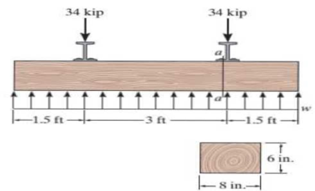
Railroad tics must be designed to resist large shear loadings. It the tie is subjected to the 34-kip rail loadings and an assumed uniformly distributed ground reaction, determine the intensity w for equilibrium, and calculate the maximum shear stress in the tie at section a–a. which is located just to the left of the rail.
Prob. 12-26
Expert Solution & Answer
Want to see the full answer?
Check out a sample textbook solution
Students have asked these similar questions
The railcar docklight is supported by the 1/8-in.-diameter pin at A. If the lamp weighs 4.1 lb, and the extension arm AB has a weight of 0.6 lb/ft.
3 ft
-1.25 in
Part A
Determine the average shear stress in the pin needed to support the lamp. Hint:The shear force in the pin is caused by the couple moment required for equilibrium at A.
Express your answer to three significant figures and include appropriate units.
Value
Units
The friction pad A is used to support the member,which is subjected to an axial force of P = 2 kN. Thepad is made from a material having a modulus ofelasticity of E = 4 MPa and Poisson’s ratio n = 0.4.If slipping does not occur, determine the normaland shear strains in the pad. The width is 50 mm.Assume that the material is linearly elastic. Also,neglect the effect of the moment acting on the pad.
Determine the normal stress and shear stress acting on the inclined plane AB. Solve the problem using the method of equilibrium described in Sec.
Chapter 12 Solutions
Statics and Mechanics of Materials (5th Edition)
Ch. 12.2 - In each case, calculate the value of Q and t that...Ch. 12.2 - If the beam is subjected to a shear force of V =...Ch. 12.2 - Prob. 2FPCh. 12.2 - Determine the absolute maximum shear stress in the...Ch. 12.2 - If the beam is subjected to a shear force of V =...Ch. 12.2 - If the beam is made from four plates and subjected...Ch. 12.2 - If the wide-flange beam is subjected to a shear of...Ch. 12.2 - If the wide-flange beam is subjected to a shear of...Ch. 12.2 - If the wide-flange beam is subjected to a shear of...Ch. 12.2 - If the beam is subjected to a shear of V = 30kN,...
Ch. 12.2 - If the wide-flange beam is subjected to a shear of...Ch. 12.2 - The wood beam has an allowable shear stress of...Ch. 12.2 - The shaft is supported by a thrust bearing at A...Ch. 12.2 - The shaft is supported by a thrust bearing at A...Ch. 12.2 - Determine the largest shear force V that the...Ch. 12.2 - If the applied shear force V = 18 kip, determine...Ch. 12.2 - The overhang beam is subjected to the uniform...Ch. 12.2 - The beam is made from a polymer and is subjected...Ch. 12.2 - Determine the maximum shear stress in the strut if...Ch. 12.2 - Determine the maximum shear force V that the strut...Ch. 12.2 - Prob. 15PCh. 12.2 - Plot the shear-stress distribution over the cross...Ch. 12.2 - Prob. 17PCh. 12.2 - If the wide-flange beam is subjected to a shear of...Ch. 12.2 - If the wide-flange beam is subjected to a shear of...Ch. 12.2 - Determine the length of the cantilevered beam so...Ch. 12.2 - If the beam is made from wood having an allowable...Ch. 12.2 - Determine the largest intensity w of the...Ch. 12.2 - If w = 800 lb/ft, determine the absolute maximum...Ch. 12.2 - Determine the shear stress at point B on the web...Ch. 12.2 - Determine the maximum shear stress acting at...Ch. 12.2 - Railroad tics must be designed to resist large...Ch. 12.2 - Prob. 27PCh. 12.2 - Prob. 28PCh. 12.2 - Determine the maximum shear stress in the T-beam...Ch. 12.2 - Determine the maximum shear stress in the T-beam...Ch. 12.2 - Prob. 31PCh. 12.3 - The two identical boards are bolted together to...Ch. 12.3 - Two identical 20-mm-thick plates are bolted to the...Ch. 12.3 - Prob. 8FPCh. 12.3 - Prob. 9FPCh. 12.3 - The beam is constructed from two boards fastened...Ch. 12.3 - The beam is constructed from two boards fastened...Ch. 12.3 - The beam is constructed from three boards. If it...Ch. 12.3 - The beam is constructed from three boards....Ch. 12.3 - Prob. 36PCh. 12.3 - The double T-beam is fabricated by welding the...Ch. 12.3 - The beam is constructed from three boards....Ch. 12.3 - A beam is constructed from three boards bolted...Ch. 12.3 - The simply supported beam is built up from three...Ch. 12.3 - Prob. 41PCh. 12.3 - Prob. 42PCh. 12.3 - Prob. 43PCh. 12.3 - The box beam is constructed from four boards that...Ch. 12.3 - The member consists of two plastic channel strips...Ch. 12.3 - The member consists of two plastic channel strips...Ch. 12.3 - Prob. 47PCh. 12.3 - Prob. 48PCh. 12 - The beam is fabricated from four boards nailed...Ch. 12 - Prob. 2RPCh. 12 - Prob. 3RPCh. 12 - Prob. 4RPCh. 12 - Prob. 5RPCh. 12 - Prob. 6RPCh. 12 - Prob. 7RPCh. 12 - The member consists of two triangular plastic...Ch. 12 - If the pipe is subjected to a shear of V = 15 kip,...
Knowledge Booster


Learn more about
Need a deep-dive on the concept behind this application? Look no further. Learn more about this topic, mechanical-engineering and related others by exploring similar questions and additional content below.Similar questions
- *7-56. The steel swivel bushing in the clevator control of an airplane is held in place using a nut and washer as shown in Fig. (a). Failure of the washer A can cause the push rod to separate as shown in Fig. (b). If the average shear stress is Tng = 145 MPa, determine the force F that must be applied to the bushing that will cause this to happen. The washer is 15 mm thick. 20 mm - (a) (b)arrow_forward7-67. If the allowable shear stress for each of the 10-mm-diameter steel pins at A, B, and Cis Tllo - 90 MPa, and the allowable normal stress for the 13-mm-diameter rod is oalon - 150 MPa, determine the largest intensity w of the uniform distributed load that can be suspended from the beam. 1.2 m 0.3marrow_forwardThe railcar docklight is supported by the 1 8-in.-diameter pin at A. If the lamp weighs 4 lb, and the extension arm AB has a weight of 0.5 lb>ft, determine the average shear stress in the pin needed to support the lamp. Hint: The shear force in the pin is caused by the couple moment required for equilibrium at A.arrow_forward
- In each case, determine the largest internal shear force resisted by the bolt. Include all necessary free-body diagrams.arrow_forwardThe assembly below consists of a steel rod CB and an aluminium rod BA, each having a diameter of 12 mm. If the rod is subjected to the axial loadings at A and at the coupling B, determine the displacement of the coupling B and the end A. The unstretched length of each segment is shown below. Neglect the size of the connections at B and C, and assume that they are rigid. Est = 200 GPa, Eal = 70 GPa.arrow_forward*10-4 The link acts as part of the elevator control for a small airplane. If the attached aluminum tube has an inner diameter of 25 mm and a wall thickness of 5 mm, determine the maximum shear stress in the tube when the cable force of 600 N is applied to the cables Also, sketch the shearstress distribution aver the cros section. f00 N 75 mm imm 25 mm 75 m G00Narrow_forward
- 9-41. The 10-mm-diameter steel bolt is surrounded by a bronze sleeve. The outer diameter of this sleeve is 20 mm, and its inner diameter is 10 mm. If the yield stress for the steel is (oy) = 640 MPa, and for the bronze (oy)r = 520 MPa, determine the magnitude of the largest elastic load P that can be applied to the assembly. Eg = 200 GPa, Ep = 100 GPa. P -10 mm -20 mm Parrow_forwardF7-7. Two klentical 20-mm thick plates are bollad to the top and bottom lange to form the buili-up heam. II the beam is subjected toa shear force of V = 300 KN, determine the allowable maximum spacing s of the boits to the nearest mm. Each bolt has a shcar strength of 30 RN. F7-9. The boards are boltod together to form the bull-up heam. Ir the beam is suhjactad to a shear force of V = 15 kip. determine the allowahle maximum spacing of the bolts le the nearst in. Each bolt has a shear strength of 6 kip. I in 05 in. 200 mm 3 in. 10 m 300 mm 10 mm 20 mm 7-9 FL7arrow_forward*6-12. A reinforced concrete pier is used to support the stringers for a bridge deck. Draw the shear and moment diagrams for the pier when it is subjected to the stringer loads shown. Assume the columns at A and B exert only vertical reactions on the pier. 60 kN 60 kN 35 kN 35 kN 35 kN m1m1.5 m 1.5 m 1 m 1m 60 KN 35 KN 35 KN 35 K 6o ITT im im 12-5 kN V(KN) 525 MCKNm) 334arrow_forward
- The man has a mass of 100 kg and center of mass at G. If he holds himself in the position shown, determine the maximum tensile and compressive stress developed in the curved bar at section a–a. He is supported uniformly by twobars, each having a diameter of 25 mm. Assume the floor is smooth. Use the curved-beam formula to calculate the bending stress.arrow_forwardexplain how to find the resultant internal loading acting on the cross section at point A. Draw all necessary free-body diagrams and indicate the relevant equations of equilibrium. Do not calculate values The lettered dimensions, angles, and loads are assumed to be known. P7-1. м в -a/2--/2-arrow_forward13-50. The C-frame is used in a riveting machine. If the force at the ram on the clamp at Dis P -8 kN, sketch the stress distribution acting over the section a-a. -200 mm- 10 mm 60 mm -10 mmarrow_forward
arrow_back_ios
SEE MORE QUESTIONS
arrow_forward_ios
Recommended textbooks for you
 Elements Of ElectromagneticsMechanical EngineeringISBN:9780190698614Author:Sadiku, Matthew N. O.Publisher:Oxford University Press
 Mechanics of Materials (10th Edition)Mechanical EngineeringISBN:9780134319650Author:Russell C. HibbelerPublisher:PEARSON
 Thermodynamics: An Engineering ApproachMechanical EngineeringISBN:9781259822674Author:Yunus A. Cengel Dr., Michael A. BolesPublisher:McGraw-Hill Education
 Control Systems EngineeringMechanical EngineeringISBN:9781118170519Author:Norman S. NisePublisher:WILEY
 Mechanics of Materials (MindTap Course List)Mechanical EngineeringISBN:9781337093347Author:Barry J. Goodno, James M. GerePublisher:Cengage Learning
 Engineering Mechanics: StaticsMechanical EngineeringISBN:9781118807330Author:James L. Meriam, L. G. Kraige, J. N. BoltonPublisher:WILEY
Elements Of Electromagnetics
Mechanical Engineering
ISBN:9780190698614
Author:Sadiku, Matthew N. O.
Publisher:Oxford University Press
Mechanics of Materials (10th Edition)
Mechanical Engineering
ISBN:9780134319650
Author:Russell C. Hibbeler
Publisher:PEARSON
Thermodynamics: An Engineering Approach
Mechanical Engineering
ISBN:9781259822674
Author:Yunus A. Cengel Dr., Michael A. Boles
Publisher:McGraw-Hill Education
Control Systems Engineering
Mechanical Engineering
ISBN:9781118170519
Author:Norman S. Nise
Publisher:WILEY
Mechanics of Materials (MindTap Course List)
Mechanical Engineering
ISBN:9781337093347
Author:Barry J. Goodno, James M. Gere
Publisher:Cengage Learning
Engineering Mechanics: Statics
Mechanical Engineering
ISBN:9781118807330
Author:James L. Meriam, L. G. Kraige, J. N. Bolton
Publisher:WILEY
An Introduction to Stress and Strain; Author: The Efficient Engineer;https://www.youtube.com/watch?v=aQf6Q8t1FQE;License: Standard YouTube License, CC-BY