
Statics and Mechanics of Materials (5th Edition)
5th Edition
ISBN: 9780134382593
Author: Russell C. Hibbeler
Publisher: PEARSON
expand_more
expand_more
format_list_bulleted
Concept explainers
Videos
Textbook Question
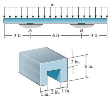
Chapter 12.2, Problem 22P
Determine the largest intensity w of the distributed load that the member can support if the allowable shear stress is τallow = 800 psi. The supports at A and B are smooth.
Probs. 12-22/23
Expert Solution & Answer
Want to see the full answer?
Check out a sample textbook solution
Students have asked these similar questions
14- effect of different carburizing treatments on the microstructure and mechanical
properties of a case produced by carburizing.
5-surface film between two surfaces is one of the main factors affecting wear.
2. Consider a polymeric membrane within a 6 cm diameter stirred ultrafiltration cell. The membrane is
30 μm thick. The membrane has pores equivalent in size to a spherical molecule with a molecular weight
of 100,000, a porosity of 80%, and a tortuosity of 2.5. On the feed side of the membrane, we have a
solution containing a protein at a concentration of 8 g L-1 with these properties: a = 3 nm and DAB = 6.0 ×
10-7 cm² s¹. The solution viscosity is 1 cP. The hydrodynamic pressure on the protein side of the
membrane is 20 pounds per square inch (psi) higher than on the filtrate side of the membrane. Assume
that the hydrodynamic pressure difference is much larger than the osmotic pressure difference
(advection >> diffusion). Determine the convective flow rate of the solution across the membrane.
1. Calculate the filtration flow rate (cm³ s¹) of a pure fluid across a 100 cm² membrane. Assume the
viscosity (µ) of the fluid is 1.8 cP. The porosity of the membrane is 40% and the thickness of the
membrane is 500 μm. The pores run straight through the membrane and these pores have a radius of
0.225 μm. The pressure drop applied across the membrane is 75 psi. (Note: 1 cP = 0.001 N s m²² = 0.001
Pa s.)
Chapter 12 Solutions
Statics and Mechanics of Materials (5th Edition)
Ch. 12.2 - In each case, calculate the value of Q and t that...Ch. 12.2 - If the beam is subjected to a shear force of V =...Ch. 12.2 - Prob. 2FPCh. 12.2 - Determine the absolute maximum shear stress in the...Ch. 12.2 - If the beam is subjected to a shear force of V =...Ch. 12.2 - If the beam is made from four plates and subjected...Ch. 12.2 - If the wide-flange beam is subjected to a shear of...Ch. 12.2 - If the wide-flange beam is subjected to a shear of...Ch. 12.2 - If the wide-flange beam is subjected to a shear of...Ch. 12.2 - If the beam is subjected to a shear of V = 30kN,...
Ch. 12.2 - If the wide-flange beam is subjected to a shear of...Ch. 12.2 - The wood beam has an allowable shear stress of...Ch. 12.2 - The shaft is supported by a thrust bearing at A...Ch. 12.2 - The shaft is supported by a thrust bearing at A...Ch. 12.2 - Determine the largest shear force V that the...Ch. 12.2 - If the applied shear force V = 18 kip, determine...Ch. 12.2 - The overhang beam is subjected to the uniform...Ch. 12.2 - The beam is made from a polymer and is subjected...Ch. 12.2 - Determine the maximum shear stress in the strut if...Ch. 12.2 - Determine the maximum shear force V that the strut...Ch. 12.2 - Prob. 15PCh. 12.2 - Plot the shear-stress distribution over the cross...Ch. 12.2 - Prob. 17PCh. 12.2 - If the wide-flange beam is subjected to a shear of...Ch. 12.2 - If the wide-flange beam is subjected to a shear of...Ch. 12.2 - Determine the length of the cantilevered beam so...Ch. 12.2 - If the beam is made from wood having an allowable...Ch. 12.2 - Determine the largest intensity w of the...Ch. 12.2 - If w = 800 lb/ft, determine the absolute maximum...Ch. 12.2 - Determine the shear stress at point B on the web...Ch. 12.2 - Determine the maximum shear stress acting at...Ch. 12.2 - Railroad tics must be designed to resist large...Ch. 12.2 - Prob. 27PCh. 12.2 - Prob. 28PCh. 12.2 - Determine the maximum shear stress in the T-beam...Ch. 12.2 - Determine the maximum shear stress in the T-beam...Ch. 12.2 - Prob. 31PCh. 12.3 - The two identical boards are bolted together to...Ch. 12.3 - Two identical 20-mm-thick plates are bolted to the...Ch. 12.3 - Prob. 8FPCh. 12.3 - Prob. 9FPCh. 12.3 - The beam is constructed from two boards fastened...Ch. 12.3 - The beam is constructed from two boards fastened...Ch. 12.3 - The beam is constructed from three boards. If it...Ch. 12.3 - The beam is constructed from three boards....Ch. 12.3 - Prob. 36PCh. 12.3 - The double T-beam is fabricated by welding the...Ch. 12.3 - The beam is constructed from three boards....Ch. 12.3 - A beam is constructed from three boards bolted...Ch. 12.3 - The simply supported beam is built up from three...Ch. 12.3 - Prob. 41PCh. 12.3 - Prob. 42PCh. 12.3 - Prob. 43PCh. 12.3 - The box beam is constructed from four boards that...Ch. 12.3 - The member consists of two plastic channel strips...Ch. 12.3 - The member consists of two plastic channel strips...Ch. 12.3 - Prob. 47PCh. 12.3 - Prob. 48PCh. 12 - The beam is fabricated from four boards nailed...Ch. 12 - Prob. 2RPCh. 12 - Prob. 3RPCh. 12 - Prob. 4RPCh. 12 - Prob. 5RPCh. 12 - Prob. 6RPCh. 12 - Prob. 7RPCh. 12 - The member consists of two triangular plastic...Ch. 12 - If the pipe is subjected to a shear of V = 15 kip,...
Knowledge Booster


Learn more about
Need a deep-dive on the concept behind this application? Look no further. Learn more about this topic, mechanical-engineering and related others by exploring similar questions and additional content below.Similar questions
- 3. Tong and Anderson (1996) obtained for BSA the following data in a polyacrylamide gel for the partition coefficient (K) as a function of the gel volume fraction (4). The BSA they used had a molecular weight of 67,000, a molecular radius of 3.6 nm, and a diffusivity of 6 × 10⁻⁷ cm2 s-1. Compare the Ogston equation K=exp + to their data and obtain an estimate for the radius of the cylindrical fibers (af) that comprise the gel. Hint: You will need to plot Ink as a function of gel volume fraction as part of your analysis. Please include your MATLAB, or other, code with your solution. Gel Volume Fraction (4) KBSA 0.00 1.0 0.025 0.35 0.05 0.09 0.06 0.05 0.075 0.017 0.085 0.02 0.105 0.03arrow_forwardAssignment 10, Question 1, Problem Book #189 Problem Statement An ideal Brayton cycle operates with no reheat, intercooling, or regeneration. The com- pressor inlet conditions are 30°C and 1 bar. The compression ratio is 11. The turbine inlet temperature is 1,300 K. Determine the turbine exit temperature, the thermal efficiency, and the back work ratio. Use an air standard analysis. Answer Table Correct Stage Description Your Answer Answer * 1 Compressor inlet enthalpy (kJ/kg) Due Date Grade (%) Weight Attempt Action/Message Part Type 1 2 1 Compressor inlet relative pressure 1 Compressor exit relative pressure 1 Compressor exit enthalpy (kJ/kg) Compressor work (kJ/kg) Turbine inlet enthalpy (kJ/kg) Dec 5, 2024 11:59 pm Dec 5, 2024 11:59 pm Dec 5, 2024 11:59 pm 0.0 0.0 1 1/5 Submit Stage 1 0.0 1 1 Dec 5, 2024 11:59 pm 0.0 1 Dec 5, 2024 11:59 pm 0.0 1 2 Turbine inlet relative pressure Dec 5, 2024 11:59 pm Dec 5, 2024 11:59 pm 0.0 1 1/5 0.0 1 2 Combustion chamber heat addition (kJ/kg) Dec…arrow_forwardAssignment 10, Question 4, Problem Book #202 Problem Statement An ideal Brayton cycle with a two-stage compressor, a two-stage turbine, and a regenerator operates with a mass flow rate of 25 kg/s. The regenerator cold inlet is at 490 K and its effectiveness is 60%. Ambient conditions are 90 kPa and 20°C. The intercooler operates at 450 kPa and the reheater operates at 550 kPa. The temperature at the exit of the combustion chamber is 1,400 K. Heat is removed in the intercooler at a rate of 2.5 MW and heat is added in the reheater at a rate of 10 MW. Determine the thermal efficiency and the back work ratio. Use a cold air standard analysis with cp = 1.005 kJ/(kg K) and k = 1.4. . Answer Table Stage Description Your Answer Correct Answer Due Date Grade (%) 1 Thermal efficiency (%) Dec 5, 2024 11:59 pm 0.0 1 Weight Attempt Action/Message 1/5 Part Type Submit 1 Back work ratio (%) Dec 5, 2024 11:59 pm 0.0 1 * Correct answers will only show after due date has passed.arrow_forward
- Assignment 10, Question 3, Problem Book #198 Problem Statement Consider a Brayton cycle with a regenerator. The regenerator has an effectiveness of 75%. The compressor inlet conditions are 1.2 bar and 300 K and the mass flowrate is 4.5 kg/s. The compressor outlet pressure is 9 bar. Both the compressor and turbine consist of a single isentropic stage. What minimum power output must be achieved before the regenerator begins to have a benefit? Use an air-standard analysis. Answer Table Correct Answer Stage Description Your Answer Due Date Grade (%) Part Weight Attempt Action/Message Туре 1 Power output (MW) Dec 5, 2024 11:59 pm 0.0 1 1/5 Submit * Correct answers will only show after due date has passed.arrow_forwardQ-3 Consider an engine operating on the ideal Diesel cycle with air as the working fluid. The volume of the cylinder is 1200 cm³ at the beginning of the Compression process, 75 cm³ at the end, and 150 cm³ after the heat addition process. Air is at 17°c and lookpa at the beginning of the compression proc ess. Determine @ The pressure at the beginning of the heat rejection process. the net work per cycle in kjⒸthe mean effective pressur. Answers @264.3 KN/m² ②0.784 kj or 544-6 kj © 697 KN 19 2 marrow_forwardIn the system shown in the (img 1), water flows through the pump at a rate of 50L/s. The permissible NPSH providedby the manufacturer with that flow is 3.6 m. Determine the maximum height Delta z above the water surface at which the Pump can be installed to operate without cavitation. Include all losses in the suction tube. What is the value of the smaller total losses? What is the value of minor-minor losses? What is the value of major-minor losses?arrow_forward
- A plastic canister whose bottom surface can be approximated as a flat surface1.9 m and 3 m long, travels through the water at 19 °C with a speed of up to 48 km/h. Determine: Drag due to friction that water exerts on the boat The power needed to overcome itarrow_forward(Fig. 1) shows the performance of a centrifugal pump for various diameters of theimpeller. For such a pump with a 5" diameter impeller, what power, in hp, would be expected to supply 5 L/s?what is its efficiency, in %?A pumping system requires 6 L/s of water with a load of 8 m, which of the pumpsof (fig. 1) would you recommend for this application?;arrow_forwardYou have the following information about a ship (image 1) Determine:a) Calculation of the block coefficient. b) Calculation of the wake coefficient. c) Determine the length of the wake.arrow_forward
- A stainless steel canoe moves horizontally along the surface of a lake at 3.7 mi/h. TheThe lake's water temperature is 60°F. The bottom of the canoe is 25 ft long and flat. The boundary layer inThe bottom of the canoe is laminar or turbulent. the value of kinematic viscosity is? the value of the Reynolds number is?arrow_forwardExample Example 1 A vertical tubular test section is to be installed in an experimental high pressure water loop. The tube is 10.16 mm i.d. and 3.66 m long heated uniformly over its EXAMPLE 73 length. An estimate of the pressure drop across the test section is required as a function of the flow-rate of water entering the test section at 204°C and 68.9 bar. (1) Calculate the pressure drop over the test section for a water flow of 0.108 kg/s with a power of 100 kW applied to the tube using (i) the homogeneous model (ii) the Martinelli-Nelson model (iii) The Thom correlation (iv) the Baroczy correlation (2) Estimate the pressure drop versus flow-rate relationship over the range 0.108 to 0.811 kg/s (2-15 USGPM) for a power of 100 kW and 200 kW applied to the tube using (i) the Martinelli-Nelson model (ii) the Baroczy correlationarrow_forward"A seismograph detects vibrations caused by seismic movements. To model this system, it is assumed that the structure undergoes a vibration with a known amplitude band frequency w (rad/s), such that its vertical displacement is given by xB=bsin(wt). This movement of the structure will produce a relative acceleration in the mass m of 2 kg, whose displacement 2 will be plotted on a roller." x= 15 kN/m Structure -WI 24 mm (Ctrl) sin(wt) b(w/w)² √√1 (w/w)] + [25(w/w)]²' "The seismograph's roller measures 60 mm, and a maximum vibration amplitude of the structure of b<5 mm is expected. Design the damper (constant c) to ensure that, for a constant oscillation, the seismograph functions correctly and the needle does not move off the roller."arrow_forward
arrow_back_ios
SEE MORE QUESTIONS
arrow_forward_ios
Recommended textbooks for you
 Elements Of ElectromagneticsMechanical EngineeringISBN:9780190698614Author:Sadiku, Matthew N. O.Publisher:Oxford University Press
 Mechanics of Materials (10th Edition)Mechanical EngineeringISBN:9780134319650Author:Russell C. HibbelerPublisher:PEARSON
 Thermodynamics: An Engineering ApproachMechanical EngineeringISBN:9781259822674Author:Yunus A. Cengel Dr., Michael A. BolesPublisher:McGraw-Hill Education
 Control Systems EngineeringMechanical EngineeringISBN:9781118170519Author:Norman S. NisePublisher:WILEY
 Mechanics of Materials (MindTap Course List)Mechanical EngineeringISBN:9781337093347Author:Barry J. Goodno, James M. GerePublisher:Cengage Learning
 Engineering Mechanics: StaticsMechanical EngineeringISBN:9781118807330Author:James L. Meriam, L. G. Kraige, J. N. BoltonPublisher:WILEY
Elements Of Electromagnetics
Mechanical Engineering
ISBN:9780190698614
Author:Sadiku, Matthew N. O.
Publisher:Oxford University Press
Mechanics of Materials (10th Edition)
Mechanical Engineering
ISBN:9780134319650
Author:Russell C. Hibbeler
Publisher:PEARSON
Thermodynamics: An Engineering Approach
Mechanical Engineering
ISBN:9781259822674
Author:Yunus A. Cengel Dr., Michael A. Boles
Publisher:McGraw-Hill Education
Control Systems Engineering
Mechanical Engineering
ISBN:9781118170519
Author:Norman S. Nise
Publisher:WILEY
Mechanics of Materials (MindTap Course List)
Mechanical Engineering
ISBN:9781337093347
Author:Barry J. Goodno, James M. Gere
Publisher:Cengage Learning
Engineering Mechanics: Statics
Mechanical Engineering
ISBN:9781118807330
Author:James L. Meriam, L. G. Kraige, J. N. Bolton
Publisher:WILEY
EVERYTHING on Axial Loading Normal Stress in 10 MINUTES - Mechanics of Materials; Author: Less Boring Lectures;https://www.youtube.com/watch?v=jQ-fNqZWrNg;License: Standard YouTube License, CC-BY