
Statics and Mechanics of Materials (5th Edition)
5th Edition
ISBN: 9780134382593
Author: Russell C. Hibbeler
Publisher: PEARSON
expand_more
expand_more
format_list_bulleted
Videos
Textbook Question
Chapter 12.2, Problem 12P
The beam is made from a polymer and is subjected to a shear of V = 7 kip. Determine the maximum shear stress in the beam and plot the shear-stress distribution over the cross section. Report the values of the shear stress every 0.5 in, of beam depth.
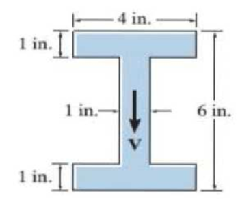
Prob. 12-12
Expert Solution & Answer
Want to see the full answer?
Check out a sample textbook solution
Students have asked these similar questions
The beam is made of Douglas fir having an allowable bending stress of sallow = 1.1 ksi and an allowable shear stress of tallow = 0.70 ksi. Determine the width b if the height h = 2b.
The beam is made from a polymer and is subjected to a shear of V = 7 kip. Determine the maximum shear stress in the beam and plot the shear-stress distribution over the cross section. Report the values of the shear stress every0.5 in. of beam depth.
The beam has a rectangular cross section with a width of 8 in. and a height of 14 in.
Determine the absolute maximum bending stress in the beam.
Chapter 12 Solutions
Statics and Mechanics of Materials (5th Edition)
Ch. 12.2 - In each case, calculate the value of Q and t that...Ch. 12.2 - If the beam is subjected to a shear force of V =...Ch. 12.2 - Prob. 2FPCh. 12.2 - Determine the absolute maximum shear stress in the...Ch. 12.2 - If the beam is subjected to a shear force of V =...Ch. 12.2 - If the beam is made from four plates and subjected...Ch. 12.2 - If the wide-flange beam is subjected to a shear of...Ch. 12.2 - If the wide-flange beam is subjected to a shear of...Ch. 12.2 - If the wide-flange beam is subjected to a shear of...Ch. 12.2 - If the beam is subjected to a shear of V = 30kN,...
Ch. 12.2 - If the wide-flange beam is subjected to a shear of...Ch. 12.2 - The wood beam has an allowable shear stress of...Ch. 12.2 - The shaft is supported by a thrust bearing at A...Ch. 12.2 - The shaft is supported by a thrust bearing at A...Ch. 12.2 - Determine the largest shear force V that the...Ch. 12.2 - If the applied shear force V = 18 kip, determine...Ch. 12.2 - The overhang beam is subjected to the uniform...Ch. 12.2 - The beam is made from a polymer and is subjected...Ch. 12.2 - Determine the maximum shear stress in the strut if...Ch. 12.2 - Determine the maximum shear force V that the strut...Ch. 12.2 - Prob. 15PCh. 12.2 - Plot the shear-stress distribution over the cross...Ch. 12.2 - Prob. 17PCh. 12.2 - If the wide-flange beam is subjected to a shear of...Ch. 12.2 - If the wide-flange beam is subjected to a shear of...Ch. 12.2 - Determine the length of the cantilevered beam so...Ch. 12.2 - If the beam is made from wood having an allowable...Ch. 12.2 - Determine the largest intensity w of the...Ch. 12.2 - If w = 800 lb/ft, determine the absolute maximum...Ch. 12.2 - Determine the shear stress at point B on the web...Ch. 12.2 - Determine the maximum shear stress acting at...Ch. 12.2 - Railroad tics must be designed to resist large...Ch. 12.2 - Prob. 27PCh. 12.2 - Prob. 28PCh. 12.2 - Determine the maximum shear stress in the T-beam...Ch. 12.2 - Determine the maximum shear stress in the T-beam...Ch. 12.2 - Prob. 31PCh. 12.3 - The two identical boards are bolted together to...Ch. 12.3 - Two identical 20-mm-thick plates are bolted to the...Ch. 12.3 - Prob. 8FPCh. 12.3 - Prob. 9FPCh. 12.3 - The beam is constructed from two boards fastened...Ch. 12.3 - The beam is constructed from two boards fastened...Ch. 12.3 - The beam is constructed from three boards. If it...Ch. 12.3 - The beam is constructed from three boards....Ch. 12.3 - Prob. 36PCh. 12.3 - The double T-beam is fabricated by welding the...Ch. 12.3 - The beam is constructed from three boards....Ch. 12.3 - A beam is constructed from three boards bolted...Ch. 12.3 - The simply supported beam is built up from three...Ch. 12.3 - Prob. 41PCh. 12.3 - Prob. 42PCh. 12.3 - Prob. 43PCh. 12.3 - The box beam is constructed from four boards that...Ch. 12.3 - The member consists of two plastic channel strips...Ch. 12.3 - The member consists of two plastic channel strips...Ch. 12.3 - Prob. 47PCh. 12.3 - Prob. 48PCh. 12 - The beam is fabricated from four boards nailed...Ch. 12 - Prob. 2RPCh. 12 - Prob. 3RPCh. 12 - Prob. 4RPCh. 12 - Prob. 5RPCh. 12 - Prob. 6RPCh. 12 - Prob. 7RPCh. 12 - The member consists of two triangular plastic...Ch. 12 - If the pipe is subjected to a shear of V = 15 kip,...
Knowledge Booster


Learn more about
Need a deep-dive on the concept behind this application? Look no further. Learn more about this topic, mechanical-engineering and related others by exploring similar questions and additional content below.Similar questions
- If the T-beam is subjected to a vertical shear of V=90kN , determine the maximum shear stress in the beam. Also, compute the shear-stress jump at the flange- web junction AB. 100 mm 100 mm A 100 mm B 75 mm 150 mmarrow_forwardDetermine the absolute maximum shear stress in the beam.arrow_forward11-22. Determine the minimum depth h of the beam to the nearest multiples of 5 mm that will safely support the loading shown. The allowable bending stress is oallow = 147 MPa and the allowable shear stress is 7allow = 70 MPa. The %3| beam has a uniform thickness of 75 mm. 60 kN/m A B- -3.6 m 1.8 marrow_forward
- *11-8. The simply supported beam is made of timber that has an allowable bending stress of ơallow = 8.4 MPa and an allowable shear stress of Tallow = 0.7 MPa. Determine its smallest dimensions to the nearest multiples of 5 mm if it is rectangular and has height-to-width ratio of 1.5. 200 kN/m A В -0.9 m- -0.9 m- 1,5 b B.arrow_forwardThe composite beam consists of a wood core and two plates of steel. If the allowable bending stress for the wood is (ơallow)w = 20 MPa, and for the steel (ơallow)st = 130 MPa, determine the maximum shear v that can be applied to the beam. Ew = 11 GPa, E = 200 GPa. 125 mm Given: (7allow),vood = 6.5 MPa E n = Ew 200(10°) 11(10°) = 18.182 1 (0.80227)(0.125) = 0.130578(10-³)m* 12 I = 20 mm- 75 mm Failure of wood : 20 mm Mc (om)max = I M(0.0625) 20(10°) M = 41.8 KN•M 0.130578(10 125mm Failure of steel : nMc (ơ1)max = I 18.182(M)(0.0625). 0.130578(10¬³) 130(10“) M = 14.9 kN •m (controls) A maximum moment that can be applied to the beam.arrow_forwardDetermine the absolute maximum bending stress in the beam. Each segment has a rectangular cross section with a base of 4 in. and height of 12 in.arrow_forward
- Determine the maximum shear stress acting in the fiberglass beam at the section where the internal shears force is maximum. (t1=15 mm, t2=20 mm, h=150 mm, b=50mm)arrow_forwardThe timber beam has a width of 6 in. Determine its height h so that it simultaneously reaches its allowable bending stress sallow = 1.50 ksi and an allowable shear stress of tallow = 50 psi. Also, what is the maximum load P that the beam can then support?arrow_forwardIf the beam has a square cross section of 9 in. on each side, determine theabsolute maximum bending stress in the beam.arrow_forward
- Determine the absolute maximum bending stress in tension and also in compression in the beam, and draw the stress distribution over the cross section at the mid span 250 mm 17.5 kN 5 kN/m Ti 30 kN•m 20 mm 300 mm 4 m 4 m 20 mmarrow_forwardIf the wide-flange beam is subjected to a shear force V = 30 kN, determine the maximum shear stress in the beam. Consider w = 200 mmarrow_forward10-26. A beam is made up of four 50 X 100-mm full-sized Douglas Fir pieces that are glued to a 25 x 500-mm Douglas Fir plywood web, as shown in the figure. Determine the maximum allowable shear and the maximum allowable bending moment that this section can carry if the allowable bending stress is 10 MPa; the allowable shear stress in plywood is 600 KN /m, and the allowable shearing stress in the glued joints is 300 kN/m^2. AIl dimensions in the figure are in mm.arrow_forward
arrow_back_ios
SEE MORE QUESTIONS
arrow_forward_ios
Recommended textbooks for you
 Elements Of ElectromagneticsMechanical EngineeringISBN:9780190698614Author:Sadiku, Matthew N. O.Publisher:Oxford University Press
 Mechanics of Materials (10th Edition)Mechanical EngineeringISBN:9780134319650Author:Russell C. HibbelerPublisher:PEARSON
 Thermodynamics: An Engineering ApproachMechanical EngineeringISBN:9781259822674Author:Yunus A. Cengel Dr., Michael A. BolesPublisher:McGraw-Hill Education
 Control Systems EngineeringMechanical EngineeringISBN:9781118170519Author:Norman S. NisePublisher:WILEY
 Mechanics of Materials (MindTap Course List)Mechanical EngineeringISBN:9781337093347Author:Barry J. Goodno, James M. GerePublisher:Cengage Learning
 Engineering Mechanics: StaticsMechanical EngineeringISBN:9781118807330Author:James L. Meriam, L. G. Kraige, J. N. BoltonPublisher:WILEY
Elements Of Electromagnetics
Mechanical Engineering
ISBN:9780190698614
Author:Sadiku, Matthew N. O.
Publisher:Oxford University Press
Mechanics of Materials (10th Edition)
Mechanical Engineering
ISBN:9780134319650
Author:Russell C. Hibbeler
Publisher:PEARSON
Thermodynamics: An Engineering Approach
Mechanical Engineering
ISBN:9781259822674
Author:Yunus A. Cengel Dr., Michael A. Boles
Publisher:McGraw-Hill Education
Control Systems Engineering
Mechanical Engineering
ISBN:9781118170519
Author:Norman S. Nise
Publisher:WILEY
Mechanics of Materials (MindTap Course List)
Mechanical Engineering
ISBN:9781337093347
Author:Barry J. Goodno, James M. Gere
Publisher:Cengage Learning
Engineering Mechanics: Statics
Mechanical Engineering
ISBN:9781118807330
Author:James L. Meriam, L. G. Kraige, J. N. Bolton
Publisher:WILEY
Mechanics of Materials Lecture: Beam Design; Author: UWMC Engineering;https://www.youtube.com/watch?v=-wVs5pvQPm4;License: Standard Youtube License