
Statics and Mechanics of Materials (5th Edition)
5th Edition
ISBN: 9780134382593
Author: Russell C. Hibbeler
Publisher: PEARSON
expand_more
expand_more
format_list_bulleted
Videos
Textbook Question
Chapter 12.2, Problem 29P
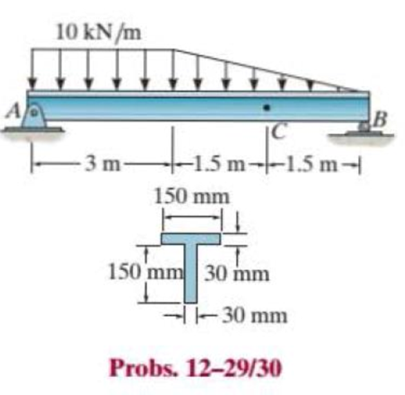
Determine the maximum shear stress in the T-beam at the critical section where the internal shear force is maximum.
Expert Solution & Answer
Want to see the full answer?
Check out a sample textbook solution
Students have asked these similar questions
1. For the simply supported beam with a T-shape cross-section as shown
below,
a- Draw the shear and moments diagram of the beam.
b- Determine the maximum normal bending stress and specify its location.
C- If the beam made from two boards determines the maximum shear stress in
the glue necessary to hold the boards together along the seam where they are
joined.
d- Determine the shear stress at point B.
4 m
6.5 kN/m
6m-
Glue
150 mm
30 mm
150 mm
30 mm
A
|100 lb
B
+2+
4 ft -
180 lb
с
- 3 -
answer item 4 only.
Chapter 12 Solutions
Statics and Mechanics of Materials (5th Edition)
Ch. 12.2 - In each case, calculate the value of Q and t that...Ch. 12.2 - If the beam is subjected to a shear force of V =...Ch. 12.2 - Prob. 2FPCh. 12.2 - Determine the absolute maximum shear stress in the...Ch. 12.2 - If the beam is subjected to a shear force of V =...Ch. 12.2 - If the beam is made from four plates and subjected...Ch. 12.2 - If the wide-flange beam is subjected to a shear of...Ch. 12.2 - If the wide-flange beam is subjected to a shear of...Ch. 12.2 - If the wide-flange beam is subjected to a shear of...Ch. 12.2 - If the beam is subjected to a shear of V = 30kN,...
Ch. 12.2 - If the wide-flange beam is subjected to a shear of...Ch. 12.2 - The wood beam has an allowable shear stress of...Ch. 12.2 - The shaft is supported by a thrust bearing at A...Ch. 12.2 - The shaft is supported by a thrust bearing at A...Ch. 12.2 - Determine the largest shear force V that the...Ch. 12.2 - If the applied shear force V = 18 kip, determine...Ch. 12.2 - The overhang beam is subjected to the uniform...Ch. 12.2 - The beam is made from a polymer and is subjected...Ch. 12.2 - Determine the maximum shear stress in the strut if...Ch. 12.2 - Determine the maximum shear force V that the strut...Ch. 12.2 - Prob. 15PCh. 12.2 - Plot the shear-stress distribution over the cross...Ch. 12.2 - Prob. 17PCh. 12.2 - If the wide-flange beam is subjected to a shear of...Ch. 12.2 - If the wide-flange beam is subjected to a shear of...Ch. 12.2 - Determine the length of the cantilevered beam so...Ch. 12.2 - If the beam is made from wood having an allowable...Ch. 12.2 - Determine the largest intensity w of the...Ch. 12.2 - If w = 800 lb/ft, determine the absolute maximum...Ch. 12.2 - Determine the shear stress at point B on the web...Ch. 12.2 - Determine the maximum shear stress acting at...Ch. 12.2 - Railroad tics must be designed to resist large...Ch. 12.2 - Prob. 27PCh. 12.2 - Prob. 28PCh. 12.2 - Determine the maximum shear stress in the T-beam...Ch. 12.2 - Determine the maximum shear stress in the T-beam...Ch. 12.2 - Prob. 31PCh. 12.3 - The two identical boards are bolted together to...Ch. 12.3 - Two identical 20-mm-thick plates are bolted to the...Ch. 12.3 - Prob. 8FPCh. 12.3 - Prob. 9FPCh. 12.3 - The beam is constructed from two boards fastened...Ch. 12.3 - The beam is constructed from two boards fastened...Ch. 12.3 - The beam is constructed from three boards. If it...Ch. 12.3 - The beam is constructed from three boards....Ch. 12.3 - Prob. 36PCh. 12.3 - The double T-beam is fabricated by welding the...Ch. 12.3 - The beam is constructed from three boards....Ch. 12.3 - A beam is constructed from three boards bolted...Ch. 12.3 - The simply supported beam is built up from three...Ch. 12.3 - Prob. 41PCh. 12.3 - Prob. 42PCh. 12.3 - Prob. 43PCh. 12.3 - The box beam is constructed from four boards that...Ch. 12.3 - The member consists of two plastic channel strips...Ch. 12.3 - The member consists of two plastic channel strips...Ch. 12.3 - Prob. 47PCh. 12.3 - Prob. 48PCh. 12 - The beam is fabricated from four boards nailed...Ch. 12 - Prob. 2RPCh. 12 - Prob. 3RPCh. 12 - Prob. 4RPCh. 12 - Prob. 5RPCh. 12 - Prob. 6RPCh. 12 - Prob. 7RPCh. 12 - The member consists of two triangular plastic...Ch. 12 - If the pipe is subjected to a shear of V = 15 kip,...
Knowledge Booster


Learn more about
Need a deep-dive on the concept behind this application? Look no further. Learn more about this topic, mechanical-engineering and related others by exploring similar questions and additional content below.Similar questions
- The simply supported joist is used in the construction of a floor for a building. In order to keep the floor low with respect to the sill beams C and D, the ends of the joists are notched as shown. If the allowable shear stress is tallow = 350 psi and the allowable bending stress is sallow = 1500 psi, determine the height h that will cause the beam to reach both allowable stresses at the same time. Also, what load P causes this to happen? Neglect the stressconcentration at the notch.arrow_forwardDetermine the maximum tensile (fot) and compressive (foc) stresses (psi) developed in the overhanging beam. The cross-section is an inverted T with the given properties 1,500 lb 3,000 lb 1,000 lb 7 in N.A. 2 in 6 ft 6 ft = 84 in R1 R2 3.arrow_forward10 kN/m The T-beam supports the distributed loading shown. (a) At section C, determine the average shear stress at the top of the stem, just below the flange. B (b) Determine the absolute maximum shear stress in the beam at the cross section where the internal shear force is max- 3 m 2 m 2 m- imum. 150 mm 150 mm 30 mm 20 mmarrow_forward
- Determine the maximum stress produced by the loads and create the shear and moment diagram for the cantilever beam system using the method of superposition.arrow_forwardDetermine the internal shear force (in kN) at point E in the compound beam shown below. Make sure to include a negative sign when appropriate. 3.2 kN/m 3.0m E 3.0m a B 1.0m 10 kN IC F 25 kN-m -2 m-2 m. Darrow_forwardDetermine the maximum tensile and compressive stresses developed in the overhanging beam that is loaded and has the cross- sectional properties as shown. 1600 lb 4000 lb 2 in N.A. 6 in 6 ft R I- 90 in 6 ft tensile stress = 3, 840 psi and compressive stress = 7, 680 psi tensile stress = 1, 280 psi and compressive stress = 2,560 psi tensile stress = 7, 680 psi and compressive stress = 3, 840 psi tensile stress = 7, 680 psi and compressive stress = 2, 560 psiarrow_forward
- Give the expression for the shear force, V = V(x), and the bending moment,M = M(x), as a function of the distance, x, measured from point A.Hint: Find the expressions of shear force and bending moment in each section:AB (0< x <4), BC (4 <x <7) and CD (7< x <10)arrow_forwardDetermine the flexural stress and shear stress of the beam loaded as shown in the figurearrow_forwardDetermine the absolute maximum normal stress (in unit of MPa) in the beam with external loadings shown below. The beam has a uniform square cross-section with lateral size a = 0.2 m. Note: (1) the shear and moment diagrams can be calculated by either section method or graphical method; (2) there is a concentrated load at point A and a bending moment at point C. 20 kN w = 20 kN/m Mc = = 80 kN · m || В A¬Q C y 2 m 2 m 2 marrow_forward
- Determine the maximum shear stress acting in the fiberglass beam at the section where the internal shears force is maximum. (t1=15 mm, t2=20 mm, h=150 mm, b=50mm)arrow_forwardIn a 2.5 cantilevered I-beam, 2500 kg weight is applied at 0.75 meter from the free end. If the allowable stress in beam is 120 Mpa, determine the section modulus and The base and height of the beam if the base is 75% of its height mm.arrow_forwardIf the beam is subjected to a shear force of V = 40 kN, a. Compute the shear stress at the web and flange interface b. Compute the shear stress 10 mm below the uppermost part of the cross section of the beam 200 mm 30 mm 280 mm 25 mmarrow_forward
arrow_back_ios
SEE MORE QUESTIONS
arrow_forward_ios
Recommended textbooks for you
 Elements Of ElectromagneticsMechanical EngineeringISBN:9780190698614Author:Sadiku, Matthew N. O.Publisher:Oxford University Press
 Mechanics of Materials (10th Edition)Mechanical EngineeringISBN:9780134319650Author:Russell C. HibbelerPublisher:PEARSON
 Thermodynamics: An Engineering ApproachMechanical EngineeringISBN:9781259822674Author:Yunus A. Cengel Dr., Michael A. BolesPublisher:McGraw-Hill Education
 Control Systems EngineeringMechanical EngineeringISBN:9781118170519Author:Norman S. NisePublisher:WILEY
 Mechanics of Materials (MindTap Course List)Mechanical EngineeringISBN:9781337093347Author:Barry J. Goodno, James M. GerePublisher:Cengage Learning
 Engineering Mechanics: StaticsMechanical EngineeringISBN:9781118807330Author:James L. Meriam, L. G. Kraige, J. N. BoltonPublisher:WILEY
Elements Of Electromagnetics
Mechanical Engineering
ISBN:9780190698614
Author:Sadiku, Matthew N. O.
Publisher:Oxford University Press
Mechanics of Materials (10th Edition)
Mechanical Engineering
ISBN:9780134319650
Author:Russell C. Hibbeler
Publisher:PEARSON
Thermodynamics: An Engineering Approach
Mechanical Engineering
ISBN:9781259822674
Author:Yunus A. Cengel Dr., Michael A. Boles
Publisher:McGraw-Hill Education
Control Systems Engineering
Mechanical Engineering
ISBN:9781118170519
Author:Norman S. Nise
Publisher:WILEY
Mechanics of Materials (MindTap Course List)
Mechanical Engineering
ISBN:9781337093347
Author:Barry J. Goodno, James M. Gere
Publisher:Cengage Learning
Engineering Mechanics: Statics
Mechanical Engineering
ISBN:9781118807330
Author:James L. Meriam, L. G. Kraige, J. N. Bolton
Publisher:WILEY
Mechanics of Materials Lecture: Beam Design; Author: UWMC Engineering;https://www.youtube.com/watch?v=-wVs5pvQPm4;License: Standard Youtube License