
Statics and Mechanics of Materials (5th Edition)
5th Edition
ISBN: 9780134382593
Author: Russell C. Hibbeler
Publisher: PEARSON
expand_more
expand_more
format_list_bulleted
Videos
Textbook Question
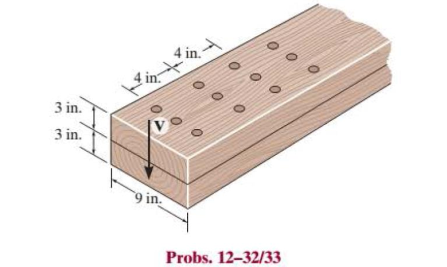
Chapter 12.3, Problem 33P
The beam is constructed from two boards fastened together at the top and bottom with three rows of nails spaced every 4 in. If a shear force of V = 900 lb is applied to the boards, determine the shear force resisted by each nail.
Expert Solution & Answer

Trending nowThis is a popular solution!

Students have asked these similar questions
The beam is constructed from two boards fastened together at the top and bottom with three rows of nails spaced every 8 in.
If an internal shear force of V = 800 lb is applied to the boards, determine the shear force resisted by each nail.
The box beam is constructed from four boards that are fastened together using nails spaced along the beam every 2 in. If each nail can resist a shear force of 50 lb, determine the largest force P that can be applied to the beam without causing failure of the nails.
20 mm
20 mm
4. The simply supported beam on the right
is built up from three boards by nailing
them together as shown. If P = 12 kN,
determine the maximum allowable spacing
s of the nails to support the load, if each
nail can resist a shear force of 1.5 kN.
1 m
m
B
100 mm
25 mm-
25 mm
200 mm
25 mm
Chapter 12 Solutions
Statics and Mechanics of Materials (5th Edition)
Ch. 12.2 - In each case, calculate the value of Q and t that...Ch. 12.2 - If the beam is subjected to a shear force of V =...Ch. 12.2 - Prob. 2FPCh. 12.2 - Determine the absolute maximum shear stress in the...Ch. 12.2 - If the beam is subjected to a shear force of V =...Ch. 12.2 - If the beam is made from four plates and subjected...Ch. 12.2 - If the wide-flange beam is subjected to a shear of...Ch. 12.2 - If the wide-flange beam is subjected to a shear of...Ch. 12.2 - If the wide-flange beam is subjected to a shear of...Ch. 12.2 - If the beam is subjected to a shear of V = 30kN,...
Ch. 12.2 - If the wide-flange beam is subjected to a shear of...Ch. 12.2 - The wood beam has an allowable shear stress of...Ch. 12.2 - The shaft is supported by a thrust bearing at A...Ch. 12.2 - The shaft is supported by a thrust bearing at A...Ch. 12.2 - Determine the largest shear force V that the...Ch. 12.2 - If the applied shear force V = 18 kip, determine...Ch. 12.2 - The overhang beam is subjected to the uniform...Ch. 12.2 - The beam is made from a polymer and is subjected...Ch. 12.2 - Determine the maximum shear stress in the strut if...Ch. 12.2 - Determine the maximum shear force V that the strut...Ch. 12.2 - Prob. 15PCh. 12.2 - Plot the shear-stress distribution over the cross...Ch. 12.2 - Prob. 17PCh. 12.2 - If the wide-flange beam is subjected to a shear of...Ch. 12.2 - If the wide-flange beam is subjected to a shear of...Ch. 12.2 - Determine the length of the cantilevered beam so...Ch. 12.2 - If the beam is made from wood having an allowable...Ch. 12.2 - Determine the largest intensity w of the...Ch. 12.2 - If w = 800 lb/ft, determine the absolute maximum...Ch. 12.2 - Determine the shear stress at point B on the web...Ch. 12.2 - Determine the maximum shear stress acting at...Ch. 12.2 - Railroad tics must be designed to resist large...Ch. 12.2 - Prob. 27PCh. 12.2 - Prob. 28PCh. 12.2 - Determine the maximum shear stress in the T-beam...Ch. 12.2 - Determine the maximum shear stress in the T-beam...Ch. 12.2 - Prob. 31PCh. 12.3 - The two identical boards are bolted together to...Ch. 12.3 - Two identical 20-mm-thick plates are bolted to the...Ch. 12.3 - Prob. 8FPCh. 12.3 - Prob. 9FPCh. 12.3 - The beam is constructed from two boards fastened...Ch. 12.3 - The beam is constructed from two boards fastened...Ch. 12.3 - The beam is constructed from three boards. If it...Ch. 12.3 - The beam is constructed from three boards....Ch. 12.3 - Prob. 36PCh. 12.3 - The double T-beam is fabricated by welding the...Ch. 12.3 - The beam is constructed from three boards....Ch. 12.3 - A beam is constructed from three boards bolted...Ch. 12.3 - The simply supported beam is built up from three...Ch. 12.3 - Prob. 41PCh. 12.3 - Prob. 42PCh. 12.3 - Prob. 43PCh. 12.3 - The box beam is constructed from four boards that...Ch. 12.3 - The member consists of two plastic channel strips...Ch. 12.3 - The member consists of two plastic channel strips...Ch. 12.3 - Prob. 47PCh. 12.3 - Prob. 48PCh. 12 - The beam is fabricated from four boards nailed...Ch. 12 - Prob. 2RPCh. 12 - Prob. 3RPCh. 12 - Prob. 4RPCh. 12 - Prob. 5RPCh. 12 - Prob. 6RPCh. 12 - Prob. 7RPCh. 12 - The member consists of two triangular plastic...Ch. 12 - If the pipe is subjected to a shear of V = 15 kip,...
Knowledge Booster


Learn more about
Need a deep-dive on the concept behind this application? Look no further. Learn more about this topic, mechanical-engineering and related others by exploring similar questions and additional content below.Similar questions
- The rows of staples AB contained in the stapler is glued together so that the maximum shear stress the glue can withstand is 12 psi. Determine the maximum force F that must be placed on the plunger in order to shear off a staple from its row and allow it to exit undeformed through the groove at C. The outer dimensions are shown in the figure below. The thickness of the staple is 0.05 in. Assume all the other parts are rigid.arrow_forwardDetermine the required diameter of the pins at A and B if the allowable shear stress for the material is tallow = 100 MPa. Both pins are subjected to double shear.arrow_forwardThe simply supported beam is built up from three boards by nailing them together as shown. If P = 12 kN, determine the maximum allowable spacing s of the nails to support that load, if each nail can resist a shear force of 1.5 kN.arrow_forward
- Two identical 20-mm-thick plates are bolted to the top and bottom flange to form the built-up beam. If the beam is subjected to a shear force of V = 300 kN, determine the maximum spacing s of the bolts to the nearest mm if eachbolt has a shear strength of 30 kN.arrow_forwardThe average shear stress in each of the 6-mm diameter bolts and along each of the four shaded shear planes is not allowed to exceed 80 MPa and 500 kPa, respectively. Determine the maximum axial force P that can be applied to the joint. 100 mm 100 mmarrow_forwardThe beam is constructed from three plastic strips. If the glue can support a shear stress of tallow = 8 kPa, determine the largest magnitude of the loads P that the beam can support.arrow_forward
- If the applied shear force V = 18 kip, determine the maximum shear stress in the member.arrow_forward1-43. If P = 5 KN. determine the average shear stress in the pins at A. B. and C. All pins are in double shear, and each has a diameter of 18 mm. 0.5 m 3P -1.5m-2 m -1.5 m- 0.5 marrow_forwardA timber company has designed a series of box beams with the geometry shown below. The beams are constructed by bonding the top and buttom boards to the edges of the vertical members at the four interfaces. Determine the maximum shear stress Tmax and the shear stress at the adhesive joints Tjoint. The vertical shear force is V = 8 kN. Given: • h₁ 100 mm h₂ = 20 mm b₁ 125 mm b₂ = 25 mm # h₂ b₂ b₁ h₁arrow_forward
- If P = 14 kN determine the average shear stress developed in the pins at A, B, and C. All pins are in double shear as shown, and each has a diameter of 15 mm 4P 4P 2P 0.5m 0.5 m 1m 1.5 m 1.5 m 30 Barrow_forwardIf P=5kN, determine the average shear stress in the pins A, B, and C. All pins are in double shear, and each as a diameter of 18 mm. P 0.5 m B 3P -1.5 m- 2 m 6P -1.5 m- P 0.5 marrow_forward2-The crimping tool is used to crimp the end of the wire E. If a force of 20 lb is applied to the handles, determine the average shear stress in the pin at A. The pin is subjected to double shear and has a diameter of 0.2 in. Only a vertical force is exerted on the wire. 20 lb III OBOD 1.5 in. 2 in. 1 in. -5 in- 20 lbarrow_forward
arrow_back_ios
SEE MORE QUESTIONS
arrow_forward_ios
Recommended textbooks for you
 Elements Of ElectromagneticsMechanical EngineeringISBN:9780190698614Author:Sadiku, Matthew N. O.Publisher:Oxford University Press
 Mechanics of Materials (10th Edition)Mechanical EngineeringISBN:9780134319650Author:Russell C. HibbelerPublisher:PEARSON
 Thermodynamics: An Engineering ApproachMechanical EngineeringISBN:9781259822674Author:Yunus A. Cengel Dr., Michael A. BolesPublisher:McGraw-Hill Education
 Control Systems EngineeringMechanical EngineeringISBN:9781118170519Author:Norman S. NisePublisher:WILEY
 Mechanics of Materials (MindTap Course List)Mechanical EngineeringISBN:9781337093347Author:Barry J. Goodno, James M. GerePublisher:Cengage Learning
 Engineering Mechanics: StaticsMechanical EngineeringISBN:9781118807330Author:James L. Meriam, L. G. Kraige, J. N. BoltonPublisher:WILEY
Elements Of Electromagnetics
Mechanical Engineering
ISBN:9780190698614
Author:Sadiku, Matthew N. O.
Publisher:Oxford University Press
Mechanics of Materials (10th Edition)
Mechanical Engineering
ISBN:9780134319650
Author:Russell C. Hibbeler
Publisher:PEARSON
Thermodynamics: An Engineering Approach
Mechanical Engineering
ISBN:9781259822674
Author:Yunus A. Cengel Dr., Michael A. Boles
Publisher:McGraw-Hill Education
Control Systems Engineering
Mechanical Engineering
ISBN:9781118170519
Author:Norman S. Nise
Publisher:WILEY
Mechanics of Materials (MindTap Course List)
Mechanical Engineering
ISBN:9781337093347
Author:Barry J. Goodno, James M. Gere
Publisher:Cengage Learning
Engineering Mechanics: Statics
Mechanical Engineering
ISBN:9781118807330
Author:James L. Meriam, L. G. Kraige, J. N. Bolton
Publisher:WILEY
Everything About TRANSVERSE SHEAR in 10 Minutes!! - Mechanics of Materials; Author: Less Boring Lectures;https://www.youtube.com/watch?v=4x0E9yvzfCM;License: Standard Youtube License