
Statics and Mechanics of Materials (5th Edition)
5th Edition
ISBN: 9780134382593
Author: Russell C. Hibbeler
Publisher: PEARSON
expand_more
expand_more
format_list_bulleted
Concept explainers
Videos
Textbook Question
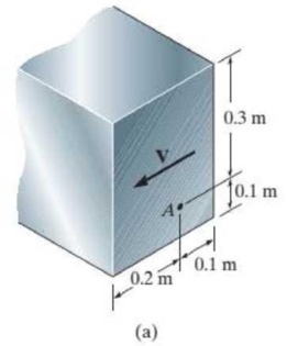
Chapter 12.2, Problem 1PP
In each case, calculate the value of Q and t that are used in the shear formula for finding the shear stress at A. Also, show how the shear stress acts on a differential volume element located at point A.
Expert Solution & Answer
Want to see the full answer?
Check out a sample textbook solution
Students have asked these similar questions
Use Mohr’s circle to determine the normal stress and shear stress acting on the inclined plane AB.
1. The pictured link acts as a part of the elevator control for a small airplane. If the
attached aluminum tube has an inner diameter of 25 mm and a wall thickness of 5
mm, determine the shear stress in the outer and inner surfaces of the tube when a
cable force of 600 N is applied to the cables. Also, sketch the shear-stress
distribution over the cross-section.
The main stress, the maximum shear stress, and the dead angle are obtained when the stress is given as shown in the picture below.Draw Mohr's circle.
Chapter 12 Solutions
Statics and Mechanics of Materials (5th Edition)
Ch. 12.2 - In each case, calculate the value of Q and t that...Ch. 12.2 - If the beam is subjected to a shear force of V =...Ch. 12.2 - Prob. 2FPCh. 12.2 - Determine the absolute maximum shear stress in the...Ch. 12.2 - If the beam is subjected to a shear force of V =...Ch. 12.2 - If the beam is made from four plates and subjected...Ch. 12.2 - If the wide-flange beam is subjected to a shear of...Ch. 12.2 - If the wide-flange beam is subjected to a shear of...Ch. 12.2 - If the wide-flange beam is subjected to a shear of...Ch. 12.2 - If the beam is subjected to a shear of V = 30kN,...
Ch. 12.2 - If the wide-flange beam is subjected to a shear of...Ch. 12.2 - The wood beam has an allowable shear stress of...Ch. 12.2 - The shaft is supported by a thrust bearing at A...Ch. 12.2 - The shaft is supported by a thrust bearing at A...Ch. 12.2 - Determine the largest shear force V that the...Ch. 12.2 - If the applied shear force V = 18 kip, determine...Ch. 12.2 - The overhang beam is subjected to the uniform...Ch. 12.2 - The beam is made from a polymer and is subjected...Ch. 12.2 - Determine the maximum shear stress in the strut if...Ch. 12.2 - Determine the maximum shear force V that the strut...Ch. 12.2 - Prob. 15PCh. 12.2 - Plot the shear-stress distribution over the cross...Ch. 12.2 - Prob. 17PCh. 12.2 - If the wide-flange beam is subjected to a shear of...Ch. 12.2 - If the wide-flange beam is subjected to a shear of...Ch. 12.2 - Determine the length of the cantilevered beam so...Ch. 12.2 - If the beam is made from wood having an allowable...Ch. 12.2 - Determine the largest intensity w of the...Ch. 12.2 - If w = 800 lb/ft, determine the absolute maximum...Ch. 12.2 - Determine the shear stress at point B on the web...Ch. 12.2 - Determine the maximum shear stress acting at...Ch. 12.2 - Railroad tics must be designed to resist large...Ch. 12.2 - Prob. 27PCh. 12.2 - Prob. 28PCh. 12.2 - Determine the maximum shear stress in the T-beam...Ch. 12.2 - Determine the maximum shear stress in the T-beam...Ch. 12.2 - Prob. 31PCh. 12.3 - The two identical boards are bolted together to...Ch. 12.3 - Two identical 20-mm-thick plates are bolted to the...Ch. 12.3 - Prob. 8FPCh. 12.3 - Prob. 9FPCh. 12.3 - The beam is constructed from two boards fastened...Ch. 12.3 - The beam is constructed from two boards fastened...Ch. 12.3 - The beam is constructed from three boards. If it...Ch. 12.3 - The beam is constructed from three boards....Ch. 12.3 - Prob. 36PCh. 12.3 - The double T-beam is fabricated by welding the...Ch. 12.3 - The beam is constructed from three boards....Ch. 12.3 - A beam is constructed from three boards bolted...Ch. 12.3 - The simply supported beam is built up from three...Ch. 12.3 - Prob. 41PCh. 12.3 - Prob. 42PCh. 12.3 - Prob. 43PCh. 12.3 - The box beam is constructed from four boards that...Ch. 12.3 - The member consists of two plastic channel strips...Ch. 12.3 - The member consists of two plastic channel strips...Ch. 12.3 - Prob. 47PCh. 12.3 - Prob. 48PCh. 12 - The beam is fabricated from four boards nailed...Ch. 12 - Prob. 2RPCh. 12 - Prob. 3RPCh. 12 - Prob. 4RPCh. 12 - Prob. 5RPCh. 12 - Prob. 6RPCh. 12 - Prob. 7RPCh. 12 - The member consists of two triangular plastic...Ch. 12 - If the pipe is subjected to a shear of V = 15 kip,...
Knowledge Booster


Learn more about
Need a deep-dive on the concept behind this application? Look no further. Learn more about this topic, mechanical-engineering and related others by exploring similar questions and additional content below.Similar questions
- Use Mohr’s circle to determine the principal stresses at the point. Also, find the corresponding orientation of the element with respect to the element shown.arrow_forwardThe forces applied to pulleys are given as shown below. Accordingly, show the stress state at point A on a 2-dimensional stress element and find the Von-Misses equivalent stress.arrow_forwardIf the allowable normal stress is 120MPa and the allowable shear stress is 60MPa, what is the resultant force at the support A?arrow_forward
- 5/5 find the normal stress at left of point C A 100 C 40 kN 50 kN 40 mm 70 10 kN 20 mm 30 mm 100 mm 300 mm 300 mm 200mm B.arrow_forwardThe T-bracket is formed by welding together two cylindrical rods AB and CD. If the allowable shear stress is 80 MPa, what is the smallest allowable diameter of rod AB? Neglect the stress caused by the transverse shear forcearrow_forwardThis problem illustrates that the factor of safety for a machine element depends on the particular point selected for analysis. Here you are to compute factors of safety, based upon the distortion-energy theory, for stress elements at A and B of the member shown in the figure. This bar is made of AISI 1006 cold-drawn steel and is loaded by the forces F= 0.55 kN, P = 4 kN, and T = 25 N·m. Given: Sy= 280 MPa. NOTE: This is a multi-part question. Once an answer is submitted, you will be unable to return to this part. 15-mm D. -100 mm- Parrow_forward
- From the stress states given, draw the 3D Mohr's circle (lable the principle normal stresses, maximum and absolute shear stresses), and sketch the principle and shear planes. σxx = 70 ksi, σzz = -50 ksi, ?xy = 50 ksi (counterclockwise)arrow_forward6. The figure below shows the geometry and loading of segment of a crankshaft. The diameter of the upper shaft is 20mm. Determine the principal stresses and the maximum shear stress at point A, which is located on the surface of the upper shaft at the zo axis. b-80 mm Xo bz = 120 mm by- 40 mm P-LOKNarrow_forwardThe box beam is subjected to the 26-kN force that is applied at the center of its width, 75 mm from each side. Determine the principal stresses at point A and show the results in an element located at this point. Use the shear formula to calculate the shear stress.arrow_forward
- For the shaft shown below, determine the normal and shear stresses acting on the element located at point A, including stress concentrations. Then draw the stress element at A with the applied stresses and determine the three principal stress (0₁, 2 and, σ3) using Mohr's circle. r = 0.0042 m, d = 0.03 m, D = 0.033 m, T = 250 Nm P = 1500 N, M = 300 Nm, A M M DEHRƏC T d T P P rarrow_forwardThe 40-mm diameter solid shaft ACBD is supported by two bearings at A and B. Due to the transmission of power to and from the shaft, the belts of the pulleys are subjected to the tension forces shown in the figure below. 1-Draw the moment and shear diagrams on the y z and y x planes 2-Determine the location and magnitude of the maximum bending (normal) stress. Hint draw the shaft cross section at that location and think of the associated stresses. 0.050 m 300 N 0.250 m 200 N 550 N 0.250 m 400 N 150m D 0.075 marrow_forwardThe cylinder for a hydraulic press has an inside diameter of 300 mm and an outside radius of 260 mm. Find the maximum shear stress in the cylinder for an internal pressure of (60 + 20) MPa.arrow_forward
arrow_back_ios
SEE MORE QUESTIONS
arrow_forward_ios
Recommended textbooks for you
 Elements Of ElectromagneticsMechanical EngineeringISBN:9780190698614Author:Sadiku, Matthew N. O.Publisher:Oxford University Press
 Mechanics of Materials (10th Edition)Mechanical EngineeringISBN:9780134319650Author:Russell C. HibbelerPublisher:PEARSON
 Thermodynamics: An Engineering ApproachMechanical EngineeringISBN:9781259822674Author:Yunus A. Cengel Dr., Michael A. BolesPublisher:McGraw-Hill Education
 Control Systems EngineeringMechanical EngineeringISBN:9781118170519Author:Norman S. NisePublisher:WILEY
 Mechanics of Materials (MindTap Course List)Mechanical EngineeringISBN:9781337093347Author:Barry J. Goodno, James M. GerePublisher:Cengage Learning
 Engineering Mechanics: StaticsMechanical EngineeringISBN:9781118807330Author:James L. Meriam, L. G. Kraige, J. N. BoltonPublisher:WILEY
Elements Of Electromagnetics
Mechanical Engineering
ISBN:9780190698614
Author:Sadiku, Matthew N. O.
Publisher:Oxford University Press
Mechanics of Materials (10th Edition)
Mechanical Engineering
ISBN:9780134319650
Author:Russell C. Hibbeler
Publisher:PEARSON
Thermodynamics: An Engineering Approach
Mechanical Engineering
ISBN:9781259822674
Author:Yunus A. Cengel Dr., Michael A. Boles
Publisher:McGraw-Hill Education
Control Systems Engineering
Mechanical Engineering
ISBN:9781118170519
Author:Norman S. Nise
Publisher:WILEY
Mechanics of Materials (MindTap Course List)
Mechanical Engineering
ISBN:9781337093347
Author:Barry J. Goodno, James M. Gere
Publisher:Cengage Learning
Engineering Mechanics: Statics
Mechanical Engineering
ISBN:9781118807330
Author:James L. Meriam, L. G. Kraige, J. N. Bolton
Publisher:WILEY
Understanding Torsion; Author: The Efficient Engineer;https://www.youtube.com/watch?v=1YTKedLQOa0;License: Standard YouTube License, CC-BY