
Statics and Mechanics of Materials (5th Edition)
5th Edition
ISBN: 9780134382593
Author: Russell C. Hibbeler
Publisher: PEARSON
expand_more
expand_more
format_list_bulleted
Videos
Textbook Question
Chapter 12.2, Problem 16P
Plot the shear-stress distribution over the cross section of a rod that has a radius c. By what factor is the maximum shear stress greater than the average shear stress acting over the cross section?
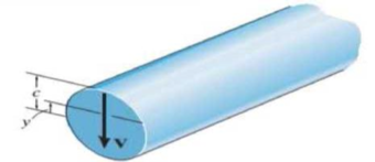
Prob. 12-16
Expert Solution & Answer
Want to see the full answer?
Check out a sample textbook solution
Students have asked these similar questions
The long bolt passes through the 70.4-mm-thick plate. If the force in the bolt shank is 9.5 KN, then the
average shear stress (MPa) along the cylindrical area of the plate defined by the section lines a-a is:
O a. 0.00
O b. 21.00
O c. 2.39
O d. 4.77
O e. 1.19
18 mm
b
b
8 mm
Time left 0:45:52
a
7 mm
YouTube
The wood beam has an allowable shear stress of 15 MPa, the maximum shear force V (kN) that can be
lind to the cross section is:
The 6061-T6 aluminum bar has a square cross section of 25 mm by 25 mm. If it is 2 m long, determine the maximum shear stress in the bar and the rotation of one end relative to the other end.
The rectangular plate is subjected to the deformation shown by the dashed line. Assume a - 575 mm, Ax- 1.8 mm, and Ay-
2.0 mm. Determine the shear strains Vxy and Yxy at point A.
Answers:
Vxy
=
Yxy"
7887
-006604
prad
urad
Chapter 12 Solutions
Statics and Mechanics of Materials (5th Edition)
Ch. 12.2 - In each case, calculate the value of Q and t that...Ch. 12.2 - If the beam is subjected to a shear force of V =...Ch. 12.2 - Prob. 2FPCh. 12.2 - Determine the absolute maximum shear stress in the...Ch. 12.2 - If the beam is subjected to a shear force of V =...Ch. 12.2 - If the beam is made from four plates and subjected...Ch. 12.2 - If the wide-flange beam is subjected to a shear of...Ch. 12.2 - If the wide-flange beam is subjected to a shear of...Ch. 12.2 - If the wide-flange beam is subjected to a shear of...Ch. 12.2 - If the beam is subjected to a shear of V = 30kN,...
Ch. 12.2 - If the wide-flange beam is subjected to a shear of...Ch. 12.2 - The wood beam has an allowable shear stress of...Ch. 12.2 - The shaft is supported by a thrust bearing at A...Ch. 12.2 - The shaft is supported by a thrust bearing at A...Ch. 12.2 - Determine the largest shear force V that the...Ch. 12.2 - If the applied shear force V = 18 kip, determine...Ch. 12.2 - The overhang beam is subjected to the uniform...Ch. 12.2 - The beam is made from a polymer and is subjected...Ch. 12.2 - Determine the maximum shear stress in the strut if...Ch. 12.2 - Determine the maximum shear force V that the strut...Ch. 12.2 - Prob. 15PCh. 12.2 - Plot the shear-stress distribution over the cross...Ch. 12.2 - Prob. 17PCh. 12.2 - If the wide-flange beam is subjected to a shear of...Ch. 12.2 - If the wide-flange beam is subjected to a shear of...Ch. 12.2 - Determine the length of the cantilevered beam so...Ch. 12.2 - If the beam is made from wood having an allowable...Ch. 12.2 - Determine the largest intensity w of the...Ch. 12.2 - If w = 800 lb/ft, determine the absolute maximum...Ch. 12.2 - Determine the shear stress at point B on the web...Ch. 12.2 - Determine the maximum shear stress acting at...Ch. 12.2 - Railroad tics must be designed to resist large...Ch. 12.2 - Prob. 27PCh. 12.2 - Prob. 28PCh. 12.2 - Determine the maximum shear stress in the T-beam...Ch. 12.2 - Determine the maximum shear stress in the T-beam...Ch. 12.2 - Prob. 31PCh. 12.3 - The two identical boards are bolted together to...Ch. 12.3 - Two identical 20-mm-thick plates are bolted to the...Ch. 12.3 - Prob. 8FPCh. 12.3 - Prob. 9FPCh. 12.3 - The beam is constructed from two boards fastened...Ch. 12.3 - The beam is constructed from two boards fastened...Ch. 12.3 - The beam is constructed from three boards. If it...Ch. 12.3 - The beam is constructed from three boards....Ch. 12.3 - Prob. 36PCh. 12.3 - The double T-beam is fabricated by welding the...Ch. 12.3 - The beam is constructed from three boards....Ch. 12.3 - A beam is constructed from three boards bolted...Ch. 12.3 - The simply supported beam is built up from three...Ch. 12.3 - Prob. 41PCh. 12.3 - Prob. 42PCh. 12.3 - Prob. 43PCh. 12.3 - The box beam is constructed from four boards that...Ch. 12.3 - The member consists of two plastic channel strips...Ch. 12.3 - The member consists of two plastic channel strips...Ch. 12.3 - Prob. 47PCh. 12.3 - Prob. 48PCh. 12 - The beam is fabricated from four boards nailed...Ch. 12 - Prob. 2RPCh. 12 - Prob. 3RPCh. 12 - Prob. 4RPCh. 12 - Prob. 5RPCh. 12 - Prob. 6RPCh. 12 - Prob. 7RPCh. 12 - The member consists of two triangular plastic...Ch. 12 - If the pipe is subjected to a shear of V = 15 kip,...
Knowledge Booster


Learn more about
Need a deep-dive on the concept behind this application? Look no further. Learn more about this topic, mechanical-engineering and related others by exploring similar questions and additional content below.Similar questions
- The double T-beam is fabricated by welding the three plates together as shown. Determine the shear stress in the weld necessary to support a shear force of V = 80 kN.arrow_forwardOnly Question 7-18arrow_forwardThe aluminum strut has a cross-sectional area in the form of a cross. It is subjected tothe Moment M = 8 KN.m. (i) Determine the bending stress acting at points A and B; (ii)Determine the maximum bending stress in the beam and sketch a three dimensional view of thestress distribution acting over the entire cross-sectional area.arrow_forward
- The A-36 steel bar consists of two segments, one of a circular cross-section of radius r, and one of square cross-section. If the bar is subjected to the axial loading of P, determine the dimensions of the square segment so that the strain energy within the square segment is the same as in the circular segment.arrow_forward8. If the allowable shear stress for each of the 10-mm-diameter steel pins at A, B, and C is Ellow = 90 MPa, and the allowable normal stress for the 13-mm-diameter rod is Glow = 150 MPa, determine the largest intensity w of the uniform distributed load that can be suspended from the beam. 1.2 m B 0.9 g Probs. 1-87/88arrow_forwardThe rod has a circular cross section. If it is made of an elastic perfectly plastic material, determine the shape factor for the rod.arrow_forward
- The assembly consists of a steel rod CB and an aluminum rod BA, each having a diameter of 15 mm. The rod is subjected to the axial loadings at A and at the coupling B. If after applying the load coupling B displaced 1.1 mm to the right, determine the change in the dimension of the cross section of steel rod CB. The unstretched length of each segment is shown in the figure. Neglect the size of the connections at B and C, and assume that they are rigid. Est = 200 GPa Vst = 0.32 %3D В A 20 kN 7 kN 3 m - 2 m·arrow_forwardThe thin-walled pipe has an inner diameter of 1.2 cm and a thickness of 0.06 cm. If it is subjected to an internal pressure of 4 MPa and the axial tension and torsional loadings shown, determine the principal stress and the absolute maximum shear stress at a point on the surface of the pipe. (15' in total) 2000 N 2000 N 8 N-m 8 N-m 1.2 cm 0.06 cmarrow_forward*2-13. The piece of rubber is originally rectangular. Determine the average shear Yzy at A if the corners B and D are subjected to the displacements that cause the rubber to distort as shown by the dashed lines. Prob. 2-13 3 mm- y D 400 mm AK -300 mm- C B 2 mm Xarrow_forward
- Determine the average shear stress developed in the nails within region AB of the beam. The nails are located on each side of the beam and are space 100 mm apart. Each nail has a diameter of 4 mm. Take P = 2kN. = Hint: Think carefully about the number of nails transferring shear stress from board-to-board. 2 kN/m A B -1.5 m 1.5 m 100 mm + 20 mm 40 mm 200 mm 20 mm 200 mmarrow_forwardThe bar has a cross-sectional area of 480(109 m². It is subjected to a triangular axial distributed loading along its length which is 0 kN/m at æ = 0 m and 9 kN/m at x = 1.5 m, and to two concentrated loads as shown. -8 kN 4 kN 0.6 m 0.9 m Part A Determine the average normal stress in the bar as a function of x for 0 m < æ < 0.6 m. 39.06x² + 6.25 39.06 – 6.25º2 o(x) = MPа 39.06 + 6.25x² 39.06x² – 6.25arrow_forwardThe beam has a square cross section and is made of wood having an allowable shear stress of Tallow= 1.4 ksi. If it is subjected to a shear of V= 1.5 kip, determine the smallest dimension a of its sides. Sketch the shear stress distribution acting across the beam's cross section. Hint: Construct the stress distribution in 2D similar to in-class examples, rather than isometrically similar to the textbook examples for clarity. V = 1.5 kiparrow_forward
arrow_back_ios
SEE MORE QUESTIONS
arrow_forward_ios
Recommended textbooks for you
 Elements Of ElectromagneticsMechanical EngineeringISBN:9780190698614Author:Sadiku, Matthew N. O.Publisher:Oxford University Press
 Mechanics of Materials (10th Edition)Mechanical EngineeringISBN:9780134319650Author:Russell C. HibbelerPublisher:PEARSON
 Thermodynamics: An Engineering ApproachMechanical EngineeringISBN:9781259822674Author:Yunus A. Cengel Dr., Michael A. BolesPublisher:McGraw-Hill Education
 Control Systems EngineeringMechanical EngineeringISBN:9781118170519Author:Norman S. NisePublisher:WILEY
 Mechanics of Materials (MindTap Course List)Mechanical EngineeringISBN:9781337093347Author:Barry J. Goodno, James M. GerePublisher:Cengage Learning
 Engineering Mechanics: StaticsMechanical EngineeringISBN:9781118807330Author:James L. Meriam, L. G. Kraige, J. N. BoltonPublisher:WILEY
Elements Of Electromagnetics
Mechanical Engineering
ISBN:9780190698614
Author:Sadiku, Matthew N. O.
Publisher:Oxford University Press
Mechanics of Materials (10th Edition)
Mechanical Engineering
ISBN:9780134319650
Author:Russell C. Hibbeler
Publisher:PEARSON
Thermodynamics: An Engineering Approach
Mechanical Engineering
ISBN:9781259822674
Author:Yunus A. Cengel Dr., Michael A. Boles
Publisher:McGraw-Hill Education
Control Systems Engineering
Mechanical Engineering
ISBN:9781118170519
Author:Norman S. Nise
Publisher:WILEY
Mechanics of Materials (MindTap Course List)
Mechanical Engineering
ISBN:9781337093347
Author:Barry J. Goodno, James M. Gere
Publisher:Cengage Learning
Engineering Mechanics: Statics
Mechanical Engineering
ISBN:9781118807330
Author:James L. Meriam, L. G. Kraige, J. N. Bolton
Publisher:WILEY
Everything About TRANSVERSE SHEAR in 10 Minutes!! - Mechanics of Materials; Author: Less Boring Lectures;https://www.youtube.com/watch?v=4x0E9yvzfCM;License: Standard Youtube License