
Mechanics of Materials, 7th Edition
7th Edition
ISBN: 9780073398235
Author: Ferdinand P. Beer, E. Russell Johnston Jr., John T. DeWolf, David F. Mazurek
Publisher: McGraw-Hill Education
expand_more
expand_more
format_list_bulleted
Videos
Textbook Question
Chapter 11.5, Problem 55P
A 160-lb diver jumps from a height of 20 in. onto end C of a diving board having the uniform cross section shown. Assuming that the diver's legs remain rigid and using E = 1.8 × 10⁶ psi, determine (a) the maximum deflection at point C, (b) the maximum normal stress in the board, (c) the equivalent static load.
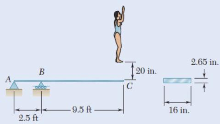
Fig. p11.55
Expert Solution & Answer
Want to see the full answer?
Check out a sample textbook solution
Students have asked these similar questions
Three bars, two made of aluminum and one made of steel, support a rigid block. An object of weight W is dropped vertically from a distance h above the rigid block. Both steel and aluminum bars have cross-sectional area of 50 mm2 and length of 0.5 m. The elastic moduli for the aluminum and steel are 76 GPa and 184 GPa, respectively.
a) If W=1000N and h=0.1m, determine whether the three bars are still safe to perform.
b) If h=0.2m, determine the maximum weight that can be dropped without causing failure to the bars
A spring of constant 15 kN/m connects points C and F of the linkage shown. Neglecting the weight of the spring and linkage, determine the force in the spring and the vertical motion of point G when a vertical downward 120-N force is applied (a) at point C ,( b) at points E and F.Fig. P10.8
TWO CYLINDRICAL ROPS, AC MADE OF ALUMINUM AND CO
MADE OF STEEL, ARE JOINED AT C ARE RESTRAINED BY
RIGID SUPPORTS AT A AND D. FOR THE LOADING SHOWN
AND KNOWING THAT Ea = 10.4 x 10⁶ psi AND = 29 x 10⁰ psi,
AND D₁ (6) THE DEFLECTION
6
DETERMINE (a) THE REACTIONS
AT A
OF POINT C.
18in
A
Be
18 kips
10 in
11 in DIAMETER
с
10 in →→→→
0
14 kips
15 in. DIAMETER
8
Chapter 11 Solutions
Mechanics of Materials, 7th Edition
Ch. 11.3 - Determine the modulus of resilience for each of...Ch. 11.3 - Determine the modulus of resilience for each of...Ch. 11.3 - Determine the modulus of resilience for each of...Ch. 11.3 - Determine the modulus of resilience for each of...Ch. 11.3 - The stress-strain diagram shown has been drawn...Ch. 11.3 - The stress-strain diagram shown has been drawn...Ch. 11.3 - Prob. 7PCh. 11.3 - Prob. 8PCh. 11.3 - Using E = 29 106 psi, determine (a) the strain...Ch. 11.3 - Using E = 200 GPa, determine (a) the strain energy...
Ch. 11.3 - A 30-in. length of aluminum pipe of...Ch. 11.3 - A single 6-mm-diameter steel pin B is used to...Ch. 11.3 - Prob. 13PCh. 11.3 - Prob. 14PCh. 11.3 - The assembly ABC is made of a steel for which E =...Ch. 11.3 - Show by integration that the strain energy of the...Ch. 11.3 - Prob. 17PCh. 11.3 - Prob. 18PCh. 11.3 - Prob. 19PCh. 11.3 - 11.18 through 11.21 In the truss shown, all...Ch. 11.3 - Prob. 21PCh. 11.3 - Each member of the truss shown is made of aluminum...Ch. 11.3 - Each member of the truss shown is made of aluminum...Ch. 11.3 - 11.24 through 11.27 Taking into account only the...Ch. 11.3 - Prob. 25PCh. 11.3 - 11.24 through 11.27 Taking into account only the...Ch. 11.3 - 11.24 through 11.27 Taking into account only the...Ch. 11.3 - Prob. 28PCh. 11.3 - Prob. 29PCh. 11.3 - Prob. 30PCh. 11.3 - 11.30 and 11.31 Using E = 200 GPa, determine the...Ch. 11.3 - Assuming that the prismatic beam AB has a...Ch. 11.3 - Prob. 33PCh. 11.3 - The design specifications for the steel shaft AB...Ch. 11.3 - Show by integration that the strain energy in the...Ch. 11.3 - The state of stress shown occurs in a machine...Ch. 11.3 - Prob. 37PCh. 11.3 - The state of stress shown occurs in a machine...Ch. 11.3 - Prob. 39PCh. 11.3 - Prob. 40PCh. 11.3 - Prob. 41PCh. 11.5 - A 5-kg collar D moves along the uniform rod AB and...Ch. 11.5 - The 18-lb cylindrical block E has a horizontal...Ch. 11.5 - The cylindrical block E has a speed v0 =16 ft/s...Ch. 11.5 - Prob. 45PCh. 11.5 - Prob. 46PCh. 11.5 - The 48-kg collar G is released from rest in the...Ch. 11.5 - Prob. 48PCh. 11.5 - Prob. 49PCh. 11.5 - Prob. 50PCh. 11.5 - Prob. 51PCh. 11.5 - The 2-kg block D is dropped from the position...Ch. 11.5 - The 10-kg block D is dropped from a height h = 450...Ch. 11.5 - Prob. 54PCh. 11.5 - A 160-lb diver jumps from a height of 20 in. onto...Ch. 11.5 - Prob. 56PCh. 11.5 - A block of weight W is dropped from a height h...Ch. 11.5 - 11.58 and 11.59 Using the method of work and...Ch. 11.5 - 11.58 and 11.59 Using the method of work and...Ch. 11.5 - 11.60 and 11.61 Using the method of work and...Ch. 11.5 - 11.60 and 11.61 Using the method of work and...Ch. 11.5 - 11.62 and 11.63 Using the method of work and...Ch. 11.5 - 11.62 and 11.63 Using the method of work and...Ch. 11.5 - Using the method of work and energy, determine the...Ch. 11.5 - Using the method of work and energy, determine the...Ch. 11.5 - The 20-mm diameter steel rod BC is attached to the...Ch. 11.5 - Torques of the same magnitude T are applied to the...Ch. 11.5 - Prob. 68PCh. 11.5 - The 20-mm-diameter steel rod CD is welded to the...Ch. 11.5 - The thin-walled hollow cylindrical member AB has a...Ch. 11.5 - 11.71 and 11.72 Each member of the truss shown has...Ch. 11.5 - 11.71 and 11.72 Each member of the truss shown has...Ch. 11.5 - Each member of the truss shown is made of steel...Ch. 11.5 - Each member of the truss shown is made of steel....Ch. 11.5 - Each member of the truss shown is made of steel...Ch. 11.5 - The steel rod BC has a 24-mm diameter and the...Ch. 11.9 - 11.77 and 11.78 Using the information in Appendix...Ch. 11.9 - 11.77 and 11.78 Using the information in Appendix...Ch. 11.9 - 11.79 through 11.82 For the beam and loading...Ch. 11.9 - 11.79 through 11.82 For the beam and loading...Ch. 11.9 - 11.79 through 11.82 For the beam and loading...Ch. 11.9 - 11.79 through 11.82 For the beam and loading...Ch. 11.9 - 11.83 through 11.85 For the prismatic beam shown,...Ch. 11.9 - 11.83 through 11.85 For the prismatic beam shown,...Ch. 11.9 - 11.83 through 11.85 For the prismatic beam shown,...Ch. 11.9 - 11.86 through 11.88 For the prismatic beam shown,...Ch. 11.9 - 11.86 through 11.88 For the prismatic beam shown,...Ch. 11.9 - 11.86 through 11.88 For the prismatic beam shown,...Ch. 11.9 - For the prismatic beam shown, determine the slope...Ch. 11.9 - For the prismatic beam shown, determine the slope...Ch. 11.9 - For the beam and loading shown, determine the...Ch. 11.9 - For the beam and loading shown, determine the...Ch. 11.9 - 11.93 and 11.94 For the beam and loading shown,...Ch. 11.9 - 11.93 and 11.94 For the beam and loading shown,...Ch. 11.9 - For the beam and loading shown, determine the...Ch. 11.9 - For the beam and loading shown, determine the...Ch. 11.9 - Prob. 97PCh. 11.9 - For the beam and loading shown, determine the...Ch. 11.9 - 11.99 and 11.100 For the truss and loading shown,...Ch. 11.9 - 11.99 and 11.100 For the truss and loading shown,...Ch. 11.9 - 11.101 and 11.102 Each member of the truss shown...Ch. 11.9 - 11.101 and 11.102 Each member of the truss shown...Ch. 11.9 - 11.103 and 11.104 Each member of the truss shown...Ch. 11.9 - 11.103 and 11 104 Each member of the truss shown...Ch. 11.9 - A uniform rod of flexural rigidity EI is bent and...Ch. 11.9 - For the uniform rod and loading shown and using...Ch. 11.9 - For the beam and loading shown and using...Ch. 11.9 - Two rods AB and BC of the same flexural rigidity...Ch. 11.9 - Three rods, each of the same flexural rigidity EI,...Ch. 11.9 - Three rods, each of the same flexural rigidity EI,...Ch. 11.9 - 11.111 through 11.115 Determine the reaction at...Ch. 11.9 - 11.111 through 11.115 Determine the reaction at...Ch. 11.9 - 11.111 through 11.115 Determine the reaction at...Ch. 11.9 - 11.111 through 11.115 Determine the reaction at...Ch. 11.9 - 11.111 through 11.115 Determine the reaction at...Ch. 11.9 - For the uniform beam and loading shown, determine...Ch. 11.9 - 11.117 through 11.120 Three members of the same...Ch. 11.9 - 11.117 through 11.120 Three members of the same...Ch. 11.9 - 11.117 through 11.120 Three members of the same...Ch. 11.9 - 11.117 through 11.120 Three members of the same...Ch. 11.9 - 11.121 and 11.122 Knowing that the eight members...Ch. 11.9 - 11.121 and 11.122 Knowing that the eight members...Ch. 11 - Rod AB is made of a steel for which the yield...Ch. 11 - Each member of the truss shown is made of steel...Ch. 11 - The ship at A has just started to drill for oil on...Ch. 11 - Collar D is released from rest in the position...Ch. 11 - Each member of the truss shown is made of steel...Ch. 11 - A block of weight W is placed in contact with a...Ch. 11 - Two solid steel shafts are connected by the gears...Ch. 11 - A 160-lb diver jumps from a height of 20 in. onto...Ch. 11 - For the prismatic beam shown, determine the slope...Ch. 11 - A disk of radius a has been welded to end B of the...Ch. 11 - A uniform rod of flexural rigidity EI is bent and...Ch. 11 - The steel bar ABC has a square cross section of...
Knowledge Booster


Learn more about
Need a deep-dive on the concept behind this application? Look no further. Learn more about this topic, mechanical-engineering and related others by exploring similar questions and additional content below.Similar questions
- The length of the 2-mm diameter steel wire CD has been adjusted so that with no load applied, a gap of 1.5mm exists between the end B of the rigid beam ACB and a contact point E. knowing that E = 200 GPa, determine where a 20-kg block should be placed on the beam in order to cause contact between B and E. D 0.23 m 20 kg B с 0.08 m 0.32 marrow_forwardD Fig. P11.71 11.72 Each member of the truss shown is made of steel and has a cross- sectional area of 400 mm². Using E200 GPa, determine the deflection of point D caused by the 16-kN load. 11.73 Each member of the truss shown is made of steel and has a cross- sectional aves of 5 in² Haing F = 20 × 106 vi 16 kN Hi D11 72 1.5 m B E 0.8 marrow_forwardSolve Prob. 10.32 assuming that the 900-N vertical force is applied at C instead of E.Reference to Problem 10.32:Two bars AD and DG are connected by a pin at D and by a spring AG . Knowing that the spring is 300 mm long when unstretched and that the constant of the spring is 5 kN/m, determine the value of x corresponding to equilibrium when a 900-N load is applied at E as shown.arrow_forward
- An acrobat is walking on a tightrope of length L-20.1 m attached to supports A and B at a distance of 20.0 m apart. The combined weight of the acrobat and his balancing pole is 900 N, and the friction between his shoes and the rope is large enough to prevent him from slipping. Neglecting the weight of the rope and any elastic deformation, determine the deflection (y) and the tension in portion AC and BC of the rope for values of x from 0.5 m to 10 m using 0.5 m increments. 1. Plot deflection (y) vs. x. Turn in the plot and the table. 2. Plot tension of AC and BC vs. x. Turn in the plot and the table of x, TAC, and Tec (clearly label each). A B C 20.0 marrow_forwardA vibration isolation unit consists of two blocks ofhard rubber bonded to a plate AB as shown. A force ofmagnitude P = 24 kN causes a deflection δ = 1.5 mmof the plate AB.(a) Determine the modulus of rigidity (G)of the rubber used.(b) If a rubber having G = 19 MPa is usedand denoting P the magnitude of the forceapplied to AB and by δ the correspondingdeflection, determine the equivalent springconstant k = P/δ of the system.arrow_forwardA vibration isolation unit consists of two blocks of hard rubber with a modulus of rigidity G= 19 MPa bonded to a plate AB and to rigid supports as shown. Denoting by P the magnitude of the force applied to the plate and by δ the corresponding deflection, determine the effective spring constant, k 5 P/δ, of the system.arrow_forward
- A container of weight W is suspended from ring A. Cable BAC passes through the ring and is attached to fixed supports at B and C. Two forces P = Pi and Q = Qk are applied to the ring to maintain the container in the position shown. Knowing that W = 542 N, determine P and Q. (Hint: The tension is the same in both portions of cable BAC.) 150 mm 140 mm B 240 mm 130 mm 420 mm P Warrow_forward10.27 Each of the five struts shown consists of a solid steel rod. (a) Knowing that the strut of Fig. (1) is of a 20-mm diameter, determine the factor of safety with respect to buckling for the loading shown. (b) Determine the diameter of each of the other struts for which the factor of safety is the same as the factor of safety obtained in part a. Use E = 200 GPa. Pa-75 kN 900 mm (1) (3) (5) Fig. P10.27arrow_forwardProblem 5.79 The bent rod is supported at A, B, and C by smooth journal bearings. (Figure 1) Figure 1 ft 4 ft A B ---20₁1-381- 45 F₂ 5ft 30° 1 of 1 > Part A 01 Determine the magnitude of F2 which will cause the reaction Cy at the bearing C to be equal to zero. The bearings are in proper alignment and exert only force reactions on the rod. Set F₁ = 600 lb. Express your answer using three significant figures and include the appropriate units. F₂= 960 | MA lb 2 Submit Previous Answers Request Answer ? X Incorrect; Try Again; 4 attempts remaining Reviewarrow_forward
- PROBLEM 10.21 10.21 The uniform brass bar AB has a rectangular cross section and is supported by pins and brackets as shown. Each end of the bar can rotate freely about a horizontal axis through the pin, but rotation about a vertical axis is prevented by the brackets. (a) Determine the ratio bld for which the factor of safety is the same about the horizontal and vertical axes. (b) Determine the factor of safety if P = 8 L = 2m, d = 38 mm, and E = 105 GPa. B kN,arrow_forwardA T-shaped bracket supports a 222-N load as shown. Determine the magnitude (N) of the reaction at A when α = 43°, x = 136.37 mm, y = 241.43 mm, and z = 316.3 mm. Round off only on the final answer expressed in 3 decimal places. Instead of units, indicate the direction of the reaction at A using either U if upward or D if downward.arrow_forwardRod AB is attached to a block at A that can slide freely in the vertical slot shown. Neglecting the effect of friction and the weights of the rods, determine the value of θ corresponding to equilibrium.Fig. P10.25arrow_forward
arrow_back_ios
SEE MORE QUESTIONS
arrow_forward_ios
Recommended textbooks for you
 Elements Of ElectromagneticsMechanical EngineeringISBN:9780190698614Author:Sadiku, Matthew N. O.Publisher:Oxford University Press
 Mechanics of Materials (10th Edition)Mechanical EngineeringISBN:9780134319650Author:Russell C. HibbelerPublisher:PEARSON
 Thermodynamics: An Engineering ApproachMechanical EngineeringISBN:9781259822674Author:Yunus A. Cengel Dr., Michael A. BolesPublisher:McGraw-Hill Education
 Control Systems EngineeringMechanical EngineeringISBN:9781118170519Author:Norman S. NisePublisher:WILEY
 Mechanics of Materials (MindTap Course List)Mechanical EngineeringISBN:9781337093347Author:Barry J. Goodno, James M. GerePublisher:Cengage Learning
 Engineering Mechanics: StaticsMechanical EngineeringISBN:9781118807330Author:James L. Meriam, L. G. Kraige, J. N. BoltonPublisher:WILEY
Elements Of Electromagnetics
Mechanical Engineering
ISBN:9780190698614
Author:Sadiku, Matthew N. O.
Publisher:Oxford University Press
Mechanics of Materials (10th Edition)
Mechanical Engineering
ISBN:9780134319650
Author:Russell C. Hibbeler
Publisher:PEARSON
Thermodynamics: An Engineering Approach
Mechanical Engineering
ISBN:9781259822674
Author:Yunus A. Cengel Dr., Michael A. Boles
Publisher:McGraw-Hill Education
Control Systems Engineering
Mechanical Engineering
ISBN:9781118170519
Author:Norman S. Nise
Publisher:WILEY
Mechanics of Materials (MindTap Course List)
Mechanical Engineering
ISBN:9781337093347
Author:Barry J. Goodno, James M. Gere
Publisher:Cengage Learning
Engineering Mechanics: Statics
Mechanical Engineering
ISBN:9781118807330
Author:James L. Meriam, L. G. Kraige, J. N. Bolton
Publisher:WILEY
Mechanical SPRING DESIGN Strategy and Restrictions in Under 15 Minutes!; Author: Less Boring Lectures;https://www.youtube.com/watch?v=dsWQrzfQt3s;License: Standard Youtube License