
Mechanics of Materials, 7th Edition
7th Edition
ISBN: 9780073398235
Author: Ferdinand P. Beer, E. Russell Johnston Jr., John T. DeWolf, David F. Mazurek
Publisher: McGraw-Hill Education
expand_more
expand_more
format_list_bulleted
Videos
Textbook Question
Chapter 11.3, Problem 6P
The stress-strain diagram shown has been drawn from data obtained during a tensile test of an aluminum alloy. Using E = 72 GPa, determine (a) the modulus of resilience of the alloy, (b) the modulus of toughness of the alloy.
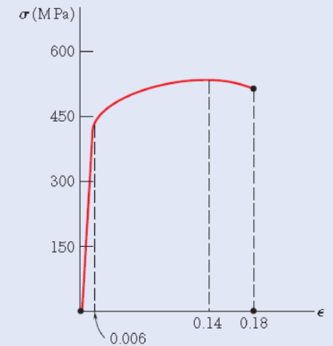
Fig P11.6
Expert Solution & Answer
Want to see the full answer?
Check out a sample textbook solution
Students have asked these similar questions
Critical flaw size corresponds to the transition between general yielding and fast fracture. If the fracture toughness of a high-strength steel can be increased by 55 % (from 100 to 155 MPa /m) without changing its yield strength of 1270 MPa, by what percentage is its critical flaw size changed?
Express your answer to three significant figures.
IVE ΑΣΦ ↓↑ vec 6
% increase = 4.33
Submit Previous Answers Request Answer
X Incorrect; Try Again
ovide Feedback
?
The engineering stress-strain curve below was obtained for a
precipitation hardened Aluminum alloy.
What is the approximate Yield Strength for this alloy in psi?
Engineering Stress Based on Original Area (psi)
50,000
45,000
40,000
35,000
30,000
25,000
20,000
15,000
10,000
5,000
0
O
0.02
0.04
0.06
Aluminum 6061-T6
0.08
0.1
0.12
Engineering Strain (in/in)
0.14
X
0.16
0.18
Calculate the Young Modulus for a mild steel. When a rod of the steel is being tested under
tensile load. The rod is 4.5m long with a diameter of diameter of 35mm and suffers an
extension of 0.9mm under a load of 50,000N
259 x 106 N/m²
259GN/m²
55MN/m²
64GN/m²
Chapter 11 Solutions
Mechanics of Materials, 7th Edition
Ch. 11.3 - Determine the modulus of resilience for each of...Ch. 11.3 - Determine the modulus of resilience for each of...Ch. 11.3 - Determine the modulus of resilience for each of...Ch. 11.3 - Determine the modulus of resilience for each of...Ch. 11.3 - The stress-strain diagram shown has been drawn...Ch. 11.3 - The stress-strain diagram shown has been drawn...Ch. 11.3 - Prob. 7PCh. 11.3 - Prob. 8PCh. 11.3 - Using E = 29 106 psi, determine (a) the strain...Ch. 11.3 - Using E = 200 GPa, determine (a) the strain energy...
Ch. 11.3 - A 30-in. length of aluminum pipe of...Ch. 11.3 - A single 6-mm-diameter steel pin B is used to...Ch. 11.3 - Prob. 13PCh. 11.3 - Prob. 14PCh. 11.3 - The assembly ABC is made of a steel for which E =...Ch. 11.3 - Show by integration that the strain energy of the...Ch. 11.3 - Prob. 17PCh. 11.3 - Prob. 18PCh. 11.3 - Prob. 19PCh. 11.3 - 11.18 through 11.21 In the truss shown, all...Ch. 11.3 - Prob. 21PCh. 11.3 - Each member of the truss shown is made of aluminum...Ch. 11.3 - Each member of the truss shown is made of aluminum...Ch. 11.3 - 11.24 through 11.27 Taking into account only the...Ch. 11.3 - Prob. 25PCh. 11.3 - 11.24 through 11.27 Taking into account only the...Ch. 11.3 - 11.24 through 11.27 Taking into account only the...Ch. 11.3 - Prob. 28PCh. 11.3 - Prob. 29PCh. 11.3 - Prob. 30PCh. 11.3 - 11.30 and 11.31 Using E = 200 GPa, determine the...Ch. 11.3 - Assuming that the prismatic beam AB has a...Ch. 11.3 - Prob. 33PCh. 11.3 - The design specifications for the steel shaft AB...Ch. 11.3 - Show by integration that the strain energy in the...Ch. 11.3 - The state of stress shown occurs in a machine...Ch. 11.3 - Prob. 37PCh. 11.3 - The state of stress shown occurs in a machine...Ch. 11.3 - Prob. 39PCh. 11.3 - Prob. 40PCh. 11.3 - Prob. 41PCh. 11.5 - A 5-kg collar D moves along the uniform rod AB and...Ch. 11.5 - The 18-lb cylindrical block E has a horizontal...Ch. 11.5 - The cylindrical block E has a speed v0 =16 ft/s...Ch. 11.5 - Prob. 45PCh. 11.5 - Prob. 46PCh. 11.5 - The 48-kg collar G is released from rest in the...Ch. 11.5 - Prob. 48PCh. 11.5 - Prob. 49PCh. 11.5 - Prob. 50PCh. 11.5 - Prob. 51PCh. 11.5 - The 2-kg block D is dropped from the position...Ch. 11.5 - The 10-kg block D is dropped from a height h = 450...Ch. 11.5 - Prob. 54PCh. 11.5 - A 160-lb diver jumps from a height of 20 in. onto...Ch. 11.5 - Prob. 56PCh. 11.5 - A block of weight W is dropped from a height h...Ch. 11.5 - 11.58 and 11.59 Using the method of work and...Ch. 11.5 - 11.58 and 11.59 Using the method of work and...Ch. 11.5 - 11.60 and 11.61 Using the method of work and...Ch. 11.5 - 11.60 and 11.61 Using the method of work and...Ch. 11.5 - 11.62 and 11.63 Using the method of work and...Ch. 11.5 - 11.62 and 11.63 Using the method of work and...Ch. 11.5 - Using the method of work and energy, determine the...Ch. 11.5 - Using the method of work and energy, determine the...Ch. 11.5 - The 20-mm diameter steel rod BC is attached to the...Ch. 11.5 - Torques of the same magnitude T are applied to the...Ch. 11.5 - Prob. 68PCh. 11.5 - The 20-mm-diameter steel rod CD is welded to the...Ch. 11.5 - The thin-walled hollow cylindrical member AB has a...Ch. 11.5 - 11.71 and 11.72 Each member of the truss shown has...Ch. 11.5 - 11.71 and 11.72 Each member of the truss shown has...Ch. 11.5 - Each member of the truss shown is made of steel...Ch. 11.5 - Each member of the truss shown is made of steel....Ch. 11.5 - Each member of the truss shown is made of steel...Ch. 11.5 - The steel rod BC has a 24-mm diameter and the...Ch. 11.9 - 11.77 and 11.78 Using the information in Appendix...Ch. 11.9 - 11.77 and 11.78 Using the information in Appendix...Ch. 11.9 - 11.79 through 11.82 For the beam and loading...Ch. 11.9 - 11.79 through 11.82 For the beam and loading...Ch. 11.9 - 11.79 through 11.82 For the beam and loading...Ch. 11.9 - 11.79 through 11.82 For the beam and loading...Ch. 11.9 - 11.83 through 11.85 For the prismatic beam shown,...Ch. 11.9 - 11.83 through 11.85 For the prismatic beam shown,...Ch. 11.9 - 11.83 through 11.85 For the prismatic beam shown,...Ch. 11.9 - 11.86 through 11.88 For the prismatic beam shown,...Ch. 11.9 - 11.86 through 11.88 For the prismatic beam shown,...Ch. 11.9 - 11.86 through 11.88 For the prismatic beam shown,...Ch. 11.9 - For the prismatic beam shown, determine the slope...Ch. 11.9 - For the prismatic beam shown, determine the slope...Ch. 11.9 - For the beam and loading shown, determine the...Ch. 11.9 - For the beam and loading shown, determine the...Ch. 11.9 - 11.93 and 11.94 For the beam and loading shown,...Ch. 11.9 - 11.93 and 11.94 For the beam and loading shown,...Ch. 11.9 - For the beam and loading shown, determine the...Ch. 11.9 - For the beam and loading shown, determine the...Ch. 11.9 - Prob. 97PCh. 11.9 - For the beam and loading shown, determine the...Ch. 11.9 - 11.99 and 11.100 For the truss and loading shown,...Ch. 11.9 - 11.99 and 11.100 For the truss and loading shown,...Ch. 11.9 - 11.101 and 11.102 Each member of the truss shown...Ch. 11.9 - 11.101 and 11.102 Each member of the truss shown...Ch. 11.9 - 11.103 and 11.104 Each member of the truss shown...Ch. 11.9 - 11.103 and 11 104 Each member of the truss shown...Ch. 11.9 - A uniform rod of flexural rigidity EI is bent and...Ch. 11.9 - For the uniform rod and loading shown and using...Ch. 11.9 - For the beam and loading shown and using...Ch. 11.9 - Two rods AB and BC of the same flexural rigidity...Ch. 11.9 - Three rods, each of the same flexural rigidity EI,...Ch. 11.9 - Three rods, each of the same flexural rigidity EI,...Ch. 11.9 - 11.111 through 11.115 Determine the reaction at...Ch. 11.9 - 11.111 through 11.115 Determine the reaction at...Ch. 11.9 - 11.111 through 11.115 Determine the reaction at...Ch. 11.9 - 11.111 through 11.115 Determine the reaction at...Ch. 11.9 - 11.111 through 11.115 Determine the reaction at...Ch. 11.9 - For the uniform beam and loading shown, determine...Ch. 11.9 - 11.117 through 11.120 Three members of the same...Ch. 11.9 - 11.117 through 11.120 Three members of the same...Ch. 11.9 - 11.117 through 11.120 Three members of the same...Ch. 11.9 - 11.117 through 11.120 Three members of the same...Ch. 11.9 - 11.121 and 11.122 Knowing that the eight members...Ch. 11.9 - 11.121 and 11.122 Knowing that the eight members...Ch. 11 - Rod AB is made of a steel for which the yield...Ch. 11 - Each member of the truss shown is made of steel...Ch. 11 - The ship at A has just started to drill for oil on...Ch. 11 - Collar D is released from rest in the position...Ch. 11 - Each member of the truss shown is made of steel...Ch. 11 - A block of weight W is placed in contact with a...Ch. 11 - Two solid steel shafts are connected by the gears...Ch. 11 - A 160-lb diver jumps from a height of 20 in. onto...Ch. 11 - For the prismatic beam shown, determine the slope...Ch. 11 - A disk of radius a has been welded to end B of the...Ch. 11 - A uniform rod of flexural rigidity EI is bent and...Ch. 11 - The steel bar ABC has a square cross section of...
Knowledge Booster


Learn more about
Need a deep-dive on the concept behind this application? Look no further. Learn more about this topic, mechanical-engineering and related others by exploring similar questions and additional content below.Similar questions
- 20. The young’s modulus of nickel is 209 gpa. Determine the length of the bar (in mm) when a force of 6.82kn is applied to a 12.5mm x 7.5mm bar originally 900 mm long without causing plastic deformation.arrow_forwardExperiments were conducted in a tension testing machine to evaluate the material properties of two metallic rods both having diameter equal to 10 mm. First rod having modulus of rigidity of the material equal to 400 tonnes/cm2 when subjected to an axial tensile force of 6 kN, the change in its diameter was observed to be 0.0018 cm. The value for the bulk modulus of the second metallic rod is same as that of the first one but modulus of elasticity 18% more. Based on the material properties calculate and compare the values of different moduli as well as Poisson’s ratio for both metallic rods. Justify your answer with reasons.arrow_forward16 Carbon nanotubes are one of the strongest materials known to engineers. They have an elastic modulus of 1.1 TPa (1TPa = 10¹2 Pa). If a carbon nanotube has a diameter of 15 nm determine the engineering stress, in GPa, sustained by the nanotube when subjected to a tensile load of 4 µN along the length of the tube. Assume that the entire cross-sectional area of the nanotube is load bearing. * = 3.14. Enter the answer rounded to one place after the decimal (xx.x). Do not enter the units. Note: This answer will be required in the next question so please note this down. Type your answer.... 17 Carbon nanotubes are one of the strongest materials known to engineers. They have an elastic modulus of 1.1 TPa (1TPa = 10¹2 Pa). Assume that the carbon nanotube is only deformed elastically under a load of 4 uN. The carbon nanotube has a length of 10 pm. what is the elongation of carbon nanotube in nanometres. Use the engineering stress from previous Q16. Enter the rounded integer answer without…arrow_forward
- You have been given the following test sample data following mechanical testing of 15 test pieces of a modified Alumina. What is the Weibull modulus of this material? Would you advise the use of this material over one with a Weibull Modulus of 19.6 and a mean failure stress of 270 MPa, if you anticipate that the peak stress on the material could be 255 MPa? Sample 1 2 3 4 5 6 7 8 9 10 11 12 13 14 15 Select one or more: a. 185 b. No Yes □d. 49 □e. 28.6 3.7 Failure Stress (MPa) 297 293 270 300 g. 22.8 260 296 265 295 280 288 263 290 298 275arrow_forward20. If the thermal deformation is permitted to occur freely, no internal forces will be induced in the body- there will strain but no stress * True False O Neither of the statements are correctarrow_forwardPart B Data taken from a stress-strain test for a ceramic are given in the table. The curve is linear between the origin and the first point. Determine the modulus of elasticity. VO AEO vec ? E = ksi Submit Request Answer Figure 1 of 1 Part C σ (ksi) e (in./in.) Determine the modulus of resilience. ΑΣφ ? vec 33.2 0.0006 45.5 0.0010 in-lb Up = in 49.4 0.0014 51.5 0.0018 Submit Request Answer 53.4 0.0022arrow_forward
- Question 1 In the strength of material, the section of the body involved is taken into consideration unlike the mechanics of materials. What is the force applied to a material divided by the area? a. normal strain b. normal stress c. strength d. shear stress e. external force Question 2 An 5.40 meter steel bar is loaded with a tensile load of 250 KN, determine the diameter of the steel bar if the elongation is limited to 4.8mm and E = 200 GPa. Choose the nearest answer. a. 42.50 mm b. 45.00 mm c. 90.00 mm d. 37.20 mm e. 105 mmarrow_forward8. A cylindrical bar of steel with a diameter of 10 mm is deformed elastically by applying a force along the bar axis. Determine the force that produces an elastic reduction in diameter of 3 X 10-³ mm. You may use material properties given in Table 6.1 below. Table 6.1 Room-Temperature Elastic and Shear Moduli and Poisson's Ratio for Various Metal Alloys Metal Alloy Aluminum Brass Copper Magnesium Nickel Steel Titanium Tungsten GPa 69 97 110 45 207 207 107 407 Modulus of Elasticity 10 psi 10 14 16 6.5 30 30 15.5 59 Shear Modulus GPa 25 37 46 17 76 83 45 160 10° psi 3.6 5.4 6.7 2.5 11.0 12.0 6.5 23.2 Poisson's Ratio 0.33 0.34 0.34 0.29 0.31 0.30 0.34 0.28arrow_forwardQuestion 1 You are working on a design team at a small orthopaedic firm. You have been asked to select a cobalt- chrome-molybdenum (CoCr) material that will not experience plastic deformation under a specific mechanical test, as follows... A tensile stress is applied along the long axis of a solid cylindrical rod that has a diameter of 10 mm. An applied load of some magnitude F produces a 7x10³ mm change in diameter (see figure below, original shape is blue, elongated shape is unshaded). Q1H: Provide a brief rationale based on calculations used to support your answer. That is, how would you explain the behavior of the "new alloy" material to your design team? Table of properties: Assume Poisson's ratio is 0.3 for all materials Process Elastic Modulus (GPa) Material CoCr F75 As cast/Annealed 210 CoCr F90 Hot forged New alloy Z X ↑ F df O 210 110 Yield Strength (MPa) 450-517 900-1200 600 Tensile Strength (MPa) 655-890 1400-1600 700arrow_forward
- Question 1 You are working on a design team at a small orthopaedic firm. You have been asked to select a cobalt- chrome-molybdenum (CoCr) material that will not experience plastic deformation under a specific mechanical test, as follows... A tensile stress is applied along the long axis of a solid cylindrical rod that has a diameter of 10 mm. An applied load of some magnitude F produces a 7x10³ mm change in diameter (see figure below, original shape is blue, elongated shape is unshaded). Q1C-D: Using the table of material properties below, calculate the magnitude of stress (o) and applied load (F) required to produce the 7x10-³ mm change in diameter for rods fabricated from F75 CoCr alloy (as cast) and F90 CoCr alloy (hot forged) materials.arrow_forwardA brass alloy is known to have a yield strength of 275 MPa (40,000 psi), a tensile strength of 380 MPa (55,000 psi), and an elastic modulus of 103 GPa (15.0×10⁶ psi). A cylindrical specimen of this alloy 8.9 mm (0.35 in.) in diameter and 241 mm (9.50 in.) long is stressed in tension and found to elongate 6.2 mm (0.24 in.). On the basis of the information given, is it possible to compute the magnitude of the load that is necessary to produce this change in length? If not, explain why. What is the yield strain? What is the test strain? b) If it is possible to calculate the load, what is the load value in N? If this computation is not possible enter a zero (0)arrow_forwardQuestion 1 You are working on a design team at a small orthopaedic firm. You have been asked to select a cobalt- chrome-molybdenum (CoCr) material that will not experience plastic deformation under a specific mechanical test, as follows... A tensile stress is applied along the long axis of a solid cylindrical rod that has a diameter of 10 mm. An applied load of some magnitude F produces a 7x10-³ mm change in diameter (see figure below, original shape is blue, elongated shape is unshaded). Q1E: Of those two materials (F75 CoCr alloy (as cast) and F90 CoCr alloy (hot forged)), which materials would you select to assure that the deformation is entirely elastic (No yield!)?arrow_forward
arrow_back_ios
SEE MORE QUESTIONS
arrow_forward_ios
Recommended textbooks for you
 Elements Of ElectromagneticsMechanical EngineeringISBN:9780190698614Author:Sadiku, Matthew N. O.Publisher:Oxford University Press
 Mechanics of Materials (10th Edition)Mechanical EngineeringISBN:9780134319650Author:Russell C. HibbelerPublisher:PEARSON
 Thermodynamics: An Engineering ApproachMechanical EngineeringISBN:9781259822674Author:Yunus A. Cengel Dr., Michael A. BolesPublisher:McGraw-Hill Education
 Control Systems EngineeringMechanical EngineeringISBN:9781118170519Author:Norman S. NisePublisher:WILEY
 Mechanics of Materials (MindTap Course List)Mechanical EngineeringISBN:9781337093347Author:Barry J. Goodno, James M. GerePublisher:Cengage Learning
 Engineering Mechanics: StaticsMechanical EngineeringISBN:9781118807330Author:James L. Meriam, L. G. Kraige, J. N. BoltonPublisher:WILEY
Elements Of Electromagnetics
Mechanical Engineering
ISBN:9780190698614
Author:Sadiku, Matthew N. O.
Publisher:Oxford University Press
Mechanics of Materials (10th Edition)
Mechanical Engineering
ISBN:9780134319650
Author:Russell C. Hibbeler
Publisher:PEARSON
Thermodynamics: An Engineering Approach
Mechanical Engineering
ISBN:9781259822674
Author:Yunus A. Cengel Dr., Michael A. Boles
Publisher:McGraw-Hill Education
Control Systems Engineering
Mechanical Engineering
ISBN:9781118170519
Author:Norman S. Nise
Publisher:WILEY
Mechanics of Materials (MindTap Course List)
Mechanical Engineering
ISBN:9781337093347
Author:Barry J. Goodno, James M. Gere
Publisher:Cengage Learning
Engineering Mechanics: Statics
Mechanical Engineering
ISBN:9781118807330
Author:James L. Meriam, L. G. Kraige, J. N. Bolton
Publisher:WILEY
Mechanical SPRING DESIGN Strategy and Restrictions in Under 15 Minutes!; Author: Less Boring Lectures;https://www.youtube.com/watch?v=dsWQrzfQt3s;License: Standard Youtube License