
Mechanics of Materials, 7th Edition
7th Edition
ISBN: 9780073398235
Author: Ferdinand P. Beer, E. Russell Johnston Jr., John T. DeWolf, David F. Mazurek
Publisher: McGraw-Hill Education
expand_more
expand_more
format_list_bulleted
Videos
Textbook Question
Chapter 11, Problem 125RP
The ship at A has just started to drill for oil on the ocean floor at a depth of 5000 ft. The steel drill pipe has an outer diameter of 8 in. and a uniform wall thickness of 0.5 in. Knowing that the top of the drill pipe rotates through two complete revolutions before the drill bit at B starts to operate and using G = 11.2 × 10⁶ psi, determine the maximum strain energy acquired by the drill pipe.
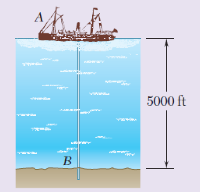
Fig. P11.125
Expert Solution & Answer
Want to see the full answer?
Check out a sample textbook solution
Students have asked these similar questions
The change in diameter of a large steel bolt is carefully measured as the nut is tightened. Knowing that E= 29 *106 psi and ν= 0.30, determine the internal force in the bolt if the diameter is observed to decrease by 0.5 *103 in
A spherical gas container having an inner diameter of 5 m and a wall thickness of 24 mm is made of steel
for which E = 200 GPa and v = 0.29. Knowing that the gage pressure in the container is increased from zero
to 1.8 MPa, determine (a) the maximum normal stress in the container, (b) the corresponding increase in the
diameter of the container.
Hint: refer back to earlier notes for relationship between strain, Poisson's ratio, and stress in two directions
Sm
The unpressurized cylindrical storage tank shown has a 5-mm wall thickness
and is made of steel having a 400-MPa ultimate strength in tension.
Determine the maximum height h to which it can be filled with water if a
factor of safety of 4.0 is desired. (Density of water = 1000 kg/m³.)
14.5 m
Hint: recall pressure (p) due to a column of water is p = yh
The maximum gage pressure is known to be 1150 psi in a spherical steel pressure vessel having a 10-in. outer diameter and a 0.25-in. wall thickness. Knowing that the ultimate stress in the steel used is σU=60 ksi, determine the factor of safety with respect to tensile failure.
Chapter 11 Solutions
Mechanics of Materials, 7th Edition
Ch. 11.3 - Determine the modulus of resilience for each of...Ch. 11.3 - Determine the modulus of resilience for each of...Ch. 11.3 - Determine the modulus of resilience for each of...Ch. 11.3 - Determine the modulus of resilience for each of...Ch. 11.3 - The stress-strain diagram shown has been drawn...Ch. 11.3 - The stress-strain diagram shown has been drawn...Ch. 11.3 - Prob. 7PCh. 11.3 - Prob. 8PCh. 11.3 - Using E = 29 106 psi, determine (a) the strain...Ch. 11.3 - Using E = 200 GPa, determine (a) the strain energy...
Ch. 11.3 - A 30-in. length of aluminum pipe of...Ch. 11.3 - A single 6-mm-diameter steel pin B is used to...Ch. 11.3 - Prob. 13PCh. 11.3 - Prob. 14PCh. 11.3 - The assembly ABC is made of a steel for which E =...Ch. 11.3 - Show by integration that the strain energy of the...Ch. 11.3 - Prob. 17PCh. 11.3 - Prob. 18PCh. 11.3 - Prob. 19PCh. 11.3 - 11.18 through 11.21 In the truss shown, all...Ch. 11.3 - Prob. 21PCh. 11.3 - Each member of the truss shown is made of aluminum...Ch. 11.3 - Each member of the truss shown is made of aluminum...Ch. 11.3 - 11.24 through 11.27 Taking into account only the...Ch. 11.3 - Prob. 25PCh. 11.3 - 11.24 through 11.27 Taking into account only the...Ch. 11.3 - 11.24 through 11.27 Taking into account only the...Ch. 11.3 - Prob. 28PCh. 11.3 - Prob. 29PCh. 11.3 - Prob. 30PCh. 11.3 - 11.30 and 11.31 Using E = 200 GPa, determine the...Ch. 11.3 - Assuming that the prismatic beam AB has a...Ch. 11.3 - Prob. 33PCh. 11.3 - The design specifications for the steel shaft AB...Ch. 11.3 - Show by integration that the strain energy in the...Ch. 11.3 - The state of stress shown occurs in a machine...Ch. 11.3 - Prob. 37PCh. 11.3 - The state of stress shown occurs in a machine...Ch. 11.3 - Prob. 39PCh. 11.3 - Prob. 40PCh. 11.3 - Prob. 41PCh. 11.5 - A 5-kg collar D moves along the uniform rod AB and...Ch. 11.5 - The 18-lb cylindrical block E has a horizontal...Ch. 11.5 - The cylindrical block E has a speed v0 =16 ft/s...Ch. 11.5 - Prob. 45PCh. 11.5 - Prob. 46PCh. 11.5 - The 48-kg collar G is released from rest in the...Ch. 11.5 - Prob. 48PCh. 11.5 - Prob. 49PCh. 11.5 - Prob. 50PCh. 11.5 - Prob. 51PCh. 11.5 - The 2-kg block D is dropped from the position...Ch. 11.5 - The 10-kg block D is dropped from a height h = 450...Ch. 11.5 - Prob. 54PCh. 11.5 - A 160-lb diver jumps from a height of 20 in. onto...Ch. 11.5 - Prob. 56PCh. 11.5 - A block of weight W is dropped from a height h...Ch. 11.5 - 11.58 and 11.59 Using the method of work and...Ch. 11.5 - 11.58 and 11.59 Using the method of work and...Ch. 11.5 - 11.60 and 11.61 Using the method of work and...Ch. 11.5 - 11.60 and 11.61 Using the method of work and...Ch. 11.5 - 11.62 and 11.63 Using the method of work and...Ch. 11.5 - 11.62 and 11.63 Using the method of work and...Ch. 11.5 - Using the method of work and energy, determine the...Ch. 11.5 - Using the method of work and energy, determine the...Ch. 11.5 - The 20-mm diameter steel rod BC is attached to the...Ch. 11.5 - Torques of the same magnitude T are applied to the...Ch. 11.5 - Prob. 68PCh. 11.5 - The 20-mm-diameter steel rod CD is welded to the...Ch. 11.5 - The thin-walled hollow cylindrical member AB has a...Ch. 11.5 - 11.71 and 11.72 Each member of the truss shown has...Ch. 11.5 - 11.71 and 11.72 Each member of the truss shown has...Ch. 11.5 - Each member of the truss shown is made of steel...Ch. 11.5 - Each member of the truss shown is made of steel....Ch. 11.5 - Each member of the truss shown is made of steel...Ch. 11.5 - The steel rod BC has a 24-mm diameter and the...Ch. 11.9 - 11.77 and 11.78 Using the information in Appendix...Ch. 11.9 - 11.77 and 11.78 Using the information in Appendix...Ch. 11.9 - 11.79 through 11.82 For the beam and loading...Ch. 11.9 - 11.79 through 11.82 For the beam and loading...Ch. 11.9 - 11.79 through 11.82 For the beam and loading...Ch. 11.9 - 11.79 through 11.82 For the beam and loading...Ch. 11.9 - 11.83 through 11.85 For the prismatic beam shown,...Ch. 11.9 - 11.83 through 11.85 For the prismatic beam shown,...Ch. 11.9 - 11.83 through 11.85 For the prismatic beam shown,...Ch. 11.9 - 11.86 through 11.88 For the prismatic beam shown,...Ch. 11.9 - 11.86 through 11.88 For the prismatic beam shown,...Ch. 11.9 - 11.86 through 11.88 For the prismatic beam shown,...Ch. 11.9 - For the prismatic beam shown, determine the slope...Ch. 11.9 - For the prismatic beam shown, determine the slope...Ch. 11.9 - For the beam and loading shown, determine the...Ch. 11.9 - For the beam and loading shown, determine the...Ch. 11.9 - 11.93 and 11.94 For the beam and loading shown,...Ch. 11.9 - 11.93 and 11.94 For the beam and loading shown,...Ch. 11.9 - For the beam and loading shown, determine the...Ch. 11.9 - For the beam and loading shown, determine the...Ch. 11.9 - Prob. 97PCh. 11.9 - For the beam and loading shown, determine the...Ch. 11.9 - 11.99 and 11.100 For the truss and loading shown,...Ch. 11.9 - 11.99 and 11.100 For the truss and loading shown,...Ch. 11.9 - 11.101 and 11.102 Each member of the truss shown...Ch. 11.9 - 11.101 and 11.102 Each member of the truss shown...Ch. 11.9 - 11.103 and 11.104 Each member of the truss shown...Ch. 11.9 - 11.103 and 11 104 Each member of the truss shown...Ch. 11.9 - A uniform rod of flexural rigidity EI is bent and...Ch. 11.9 - For the uniform rod and loading shown and using...Ch. 11.9 - For the beam and loading shown and using...Ch. 11.9 - Two rods AB and BC of the same flexural rigidity...Ch. 11.9 - Three rods, each of the same flexural rigidity EI,...Ch. 11.9 - Three rods, each of the same flexural rigidity EI,...Ch. 11.9 - 11.111 through 11.115 Determine the reaction at...Ch. 11.9 - 11.111 through 11.115 Determine the reaction at...Ch. 11.9 - 11.111 through 11.115 Determine the reaction at...Ch. 11.9 - 11.111 through 11.115 Determine the reaction at...Ch. 11.9 - 11.111 through 11.115 Determine the reaction at...Ch. 11.9 - For the uniform beam and loading shown, determine...Ch. 11.9 - 11.117 through 11.120 Three members of the same...Ch. 11.9 - 11.117 through 11.120 Three members of the same...Ch. 11.9 - 11.117 through 11.120 Three members of the same...Ch. 11.9 - 11.117 through 11.120 Three members of the same...Ch. 11.9 - 11.121 and 11.122 Knowing that the eight members...Ch. 11.9 - 11.121 and 11.122 Knowing that the eight members...Ch. 11 - Rod AB is made of a steel for which the yield...Ch. 11 - Each member of the truss shown is made of steel...Ch. 11 - The ship at A has just started to drill for oil on...Ch. 11 - Collar D is released from rest in the position...Ch. 11 - Each member of the truss shown is made of steel...Ch. 11 - A block of weight W is placed in contact with a...Ch. 11 - Two solid steel shafts are connected by the gears...Ch. 11 - A 160-lb diver jumps from a height of 20 in. onto...Ch. 11 - For the prismatic beam shown, determine the slope...Ch. 11 - A disk of radius a has been welded to end B of the...Ch. 11 - A uniform rod of flexural rigidity EI is bent and...Ch. 11 - The steel bar ABC has a square cross section of...
Knowledge Booster


Learn more about
Need a deep-dive on the concept behind this application? Look no further. Learn more about this topic, mechanical-engineering and related others by exploring similar questions and additional content below.Similar questions
- A pressure vessel containing gas at 250 psi has an outer diameter of 12 inches and a thickness of 1/16 inch. Determine absolute maximum shear stress in the pressure vessel in ksi. а. 17.7 с. 21.7 b. 19.7 d. 23.7arrow_forwardA steel gear, with 80-mm diameter rod connected to it is used to transmit 600 HP at 200 rpm. If the rod has a G = 83 GPa and length equal to 6 meters, determine the shear stress of the rodarrow_forwardRequired information Problem 07.114 - Determine the normal stress and shearing stress in the weld of a steel pressure tank. The steel pressure tank shown has a 38-in. inner diameter and a 0.375-in. wall thickness. It is given that the butt-welded seams form an angle 3 = 50° with the longitudinal axis of the tank and that the gage pressure in the tank is 200 psi. В Problem 07.114.a - Determine the normal stress perpendicular to the weld. Determine the normal stress perpendicular to the weld. The normal stress perpendicular to the weld is 2519.46 psi.arrow_forward
- 12. A single strain gage is cemented to solid 96-mm-diameter aluminum shaft at an angle B = 20° with a line parallel to the axis of the shaft. Knowing that G = 27 GPa, determine the torque T corresponding to a gage reading of 400u. 48 mm Figure P12arrow_forwardA solid 20-mm-diameter shaft is subjected to an axial load P. The shaft is made of aluminum [E = 70 GPa; v=0.33]. A strain gage is mounted on the shaft at the orientation shown in Fig. P13.77. (a) If P= 18.5 kN, determine the strain reading that would be expected from the gage. (b) If the gage indicates a strain value of ε = 950 ue, determine the axial force P applied to the shaft.arrow_forwardQ.1 A rod is made of wrought iron and is secured to the piston by a tapered rod and nut and to the crosshead by a cotter. Determine the diameter of a piston rod for a cylinder of 1.6 m diameter in which the greatest difference of steam pressure on the two sides of the piston is 0.27 N/mm². The length of the rod is 2.9 m. The modulus of elasticity is 212 KN/mm² and the factor of safety is 5.arrow_forward
- At a temperature of 32.98 °C a 0.41-mm gap exists between the ends of the rods shown. At a later time when the temperature has reached 131.06°C, determine the magnitude of the normal stress (in MPa) in the steel rod if L = 332.28 mm and M = 209 mm.arrow_forward15.3 (B). Show that the strain energy per unit volume of a material under a single direct stress is given by (stress x strain). Hence show that for a material under the action of the principal stresseso,,02 and o, the strain energy per unit volume becomes 1 Toi+o +o3 - 2v(0,02+0,03+0203)] 2E A thin cylinder 1m diameter and 3 m long is filled with a liquid to a pressure of 2 MN/m?. Assuming a yield stress for the material of 240 MN/m2 in simple tension and a safety factor of 4, determine the necessary wall thickness of the cylinder, taking the maximum shear strain energy as the criterion of failure. For the cylinder material, E = 207 GN/m2 and v 0.286. [14.4 mm.]arrow_forward9.59 In many situations it is known that the normal stress in a given direction is zero. For example, o; = 0 in the case of the thin plate shown. For this case, which is known as plane stress, show that if the strains e, and e, have been determined experimentally, we can express o, o, and e̟ as follows: €x + v€y 0, = E 1 - v2 + νε, Fig. P9.59 = E 1 v² (e, + €„)arrow_forward
- In many situations physical constraints prevent strain from occurring in a given direction. For example, εz= 0 in the case shown, where longitudinal movement of the long prism is prevented at every point. Plane sections perpendicular to the longitudinal axis remain plane and the same distance apart. Show that for this situation, which is known as plane strain, we can express σz, εx, and εy as followsarrow_forward3. a) In the composite spring shown, Spring 1 has a mean coil diameter of 36 mm and a wire diameter of 3mm. Determine the wire diameter of spring 2 if it has a mean coil diameter of 24mm and the maximum shear stress in the two springs is to be the same. 20.25N B Spring 2 Spring 1 b) If G=80 GPa and points A and B moved through 14mm and 19,94mm respectively determine: i. the number of coils in each spring ii. the effective stiffness of the composite springarrow_forwardProve that the sum of the normal strains in perpendicular directions is constant, i.e., Px + Py = Px′ + Py′arrow_forward
arrow_back_ios
SEE MORE QUESTIONS
arrow_forward_ios
Recommended textbooks for you
 Elements Of ElectromagneticsMechanical EngineeringISBN:9780190698614Author:Sadiku, Matthew N. O.Publisher:Oxford University Press
 Mechanics of Materials (10th Edition)Mechanical EngineeringISBN:9780134319650Author:Russell C. HibbelerPublisher:PEARSON
 Thermodynamics: An Engineering ApproachMechanical EngineeringISBN:9781259822674Author:Yunus A. Cengel Dr., Michael A. BolesPublisher:McGraw-Hill Education
 Control Systems EngineeringMechanical EngineeringISBN:9781118170519Author:Norman S. NisePublisher:WILEY
 Mechanics of Materials (MindTap Course List)Mechanical EngineeringISBN:9781337093347Author:Barry J. Goodno, James M. GerePublisher:Cengage Learning
 Engineering Mechanics: StaticsMechanical EngineeringISBN:9781118807330Author:James L. Meriam, L. G. Kraige, J. N. BoltonPublisher:WILEY
Elements Of Electromagnetics
Mechanical Engineering
ISBN:9780190698614
Author:Sadiku, Matthew N. O.
Publisher:Oxford University Press
Mechanics of Materials (10th Edition)
Mechanical Engineering
ISBN:9780134319650
Author:Russell C. Hibbeler
Publisher:PEARSON
Thermodynamics: An Engineering Approach
Mechanical Engineering
ISBN:9781259822674
Author:Yunus A. Cengel Dr., Michael A. Boles
Publisher:McGraw-Hill Education
Control Systems Engineering
Mechanical Engineering
ISBN:9781118170519
Author:Norman S. Nise
Publisher:WILEY
Mechanics of Materials (MindTap Course List)
Mechanical Engineering
ISBN:9781337093347
Author:Barry J. Goodno, James M. Gere
Publisher:Cengage Learning
Engineering Mechanics: Statics
Mechanical Engineering
ISBN:9781118807330
Author:James L. Meriam, L. G. Kraige, J. N. Bolton
Publisher:WILEY
Understanding Failure Theories (Tresca, von Mises etc...); Author: The Efficient Engineer;https://www.youtube.com/watch?v=xkbQnBAOFEg;License: Standard youtube license