
Mechanics of Materials, 7th Edition
7th Edition
ISBN: 9780073398235
Author: Ferdinand P. Beer, E. Russell Johnston Jr., John T. DeWolf, David F. Mazurek
Publisher: McGraw-Hill Education
expand_more
expand_more
format_list_bulleted
Videos
Textbook Question
Chapter 11.5, Problem 44P
The cylindrical block E has a speed v0 =16 ft/s when it strikes squarely the yoke BD that is attached to the
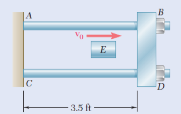
Fig. P11.43 and P11.44
Expert Solution & Answer
Want to see the full answer?
Check out a sample textbook solution
Students have asked these similar questions
Solve Prob. 8.124 assuming that the idler drum C is frozen and cannot rotate.(Reference to Problem 8.124):A recording tape passes over the 20-mm-radius drive drum B and under the idler drum C . Knowing that the coefficients of friction between the tape and the drums are μs= 0.40 and μk= 0.30 and that drum C is free to rotate, determine the smallest allowable value of P if slipping of the tape on drum B is not to occur.
Problem 10:
The 48-kg collar G is released from rest in the position shown and is stopped by plate BDF that is attached to the
20-mm-diameter steel rod CD and to the 15-mm-diameter steel rods AB and EF. Knowing that for the grade of
steel used allowable normal stress of 180 MPa and E=200 GPa, determine the largest allowable distance h.
ACE
2.5m
С
D
B
F
A spring of constant 15 kN/m connects points C and F of the linkage shown. Neglecting the weight of the spring and linkage, determine the force in the spring and the vertical motion of point G when a vertical downward 120-N force is applied (a) at point C ,( b) at points E and F.Fig. P10.8
Chapter 11 Solutions
Mechanics of Materials, 7th Edition
Ch. 11.3 - Determine the modulus of resilience for each of...Ch. 11.3 - Determine the modulus of resilience for each of...Ch. 11.3 - Determine the modulus of resilience for each of...Ch. 11.3 - Determine the modulus of resilience for each of...Ch. 11.3 - The stress-strain diagram shown has been drawn...Ch. 11.3 - The stress-strain diagram shown has been drawn...Ch. 11.3 - Prob. 7PCh. 11.3 - Prob. 8PCh. 11.3 - Using E = 29 106 psi, determine (a) the strain...Ch. 11.3 - Using E = 200 GPa, determine (a) the strain energy...
Ch. 11.3 - A 30-in. length of aluminum pipe of...Ch. 11.3 - A single 6-mm-diameter steel pin B is used to...Ch. 11.3 - Prob. 13PCh. 11.3 - Prob. 14PCh. 11.3 - The assembly ABC is made of a steel for which E =...Ch. 11.3 - Show by integration that the strain energy of the...Ch. 11.3 - Prob. 17PCh. 11.3 - Prob. 18PCh. 11.3 - Prob. 19PCh. 11.3 - 11.18 through 11.21 In the truss shown, all...Ch. 11.3 - Prob. 21PCh. 11.3 - Each member of the truss shown is made of aluminum...Ch. 11.3 - Each member of the truss shown is made of aluminum...Ch. 11.3 - 11.24 through 11.27 Taking into account only the...Ch. 11.3 - Prob. 25PCh. 11.3 - 11.24 through 11.27 Taking into account only the...Ch. 11.3 - 11.24 through 11.27 Taking into account only the...Ch. 11.3 - Prob. 28PCh. 11.3 - Prob. 29PCh. 11.3 - Prob. 30PCh. 11.3 - 11.30 and 11.31 Using E = 200 GPa, determine the...Ch. 11.3 - Assuming that the prismatic beam AB has a...Ch. 11.3 - Prob. 33PCh. 11.3 - The design specifications for the steel shaft AB...Ch. 11.3 - Show by integration that the strain energy in the...Ch. 11.3 - The state of stress shown occurs in a machine...Ch. 11.3 - Prob. 37PCh. 11.3 - The state of stress shown occurs in a machine...Ch. 11.3 - Prob. 39PCh. 11.3 - Prob. 40PCh. 11.3 - Prob. 41PCh. 11.5 - A 5-kg collar D moves along the uniform rod AB and...Ch. 11.5 - The 18-lb cylindrical block E has a horizontal...Ch. 11.5 - The cylindrical block E has a speed v0 =16 ft/s...Ch. 11.5 - Prob. 45PCh. 11.5 - Prob. 46PCh. 11.5 - The 48-kg collar G is released from rest in the...Ch. 11.5 - Prob. 48PCh. 11.5 - Prob. 49PCh. 11.5 - Prob. 50PCh. 11.5 - Prob. 51PCh. 11.5 - The 2-kg block D is dropped from the position...Ch. 11.5 - The 10-kg block D is dropped from a height h = 450...Ch. 11.5 - Prob. 54PCh. 11.5 - A 160-lb diver jumps from a height of 20 in. onto...Ch. 11.5 - Prob. 56PCh. 11.5 - A block of weight W is dropped from a height h...Ch. 11.5 - 11.58 and 11.59 Using the method of work and...Ch. 11.5 - 11.58 and 11.59 Using the method of work and...Ch. 11.5 - 11.60 and 11.61 Using the method of work and...Ch. 11.5 - 11.60 and 11.61 Using the method of work and...Ch. 11.5 - 11.62 and 11.63 Using the method of work and...Ch. 11.5 - 11.62 and 11.63 Using the method of work and...Ch. 11.5 - Using the method of work and energy, determine the...Ch. 11.5 - Using the method of work and energy, determine the...Ch. 11.5 - The 20-mm diameter steel rod BC is attached to the...Ch. 11.5 - Torques of the same magnitude T are applied to the...Ch. 11.5 - Prob. 68PCh. 11.5 - The 20-mm-diameter steel rod CD is welded to the...Ch. 11.5 - The thin-walled hollow cylindrical member AB has a...Ch. 11.5 - 11.71 and 11.72 Each member of the truss shown has...Ch. 11.5 - 11.71 and 11.72 Each member of the truss shown has...Ch. 11.5 - Each member of the truss shown is made of steel...Ch. 11.5 - Each member of the truss shown is made of steel....Ch. 11.5 - Each member of the truss shown is made of steel...Ch. 11.5 - The steel rod BC has a 24-mm diameter and the...Ch. 11.9 - 11.77 and 11.78 Using the information in Appendix...Ch. 11.9 - 11.77 and 11.78 Using the information in Appendix...Ch. 11.9 - 11.79 through 11.82 For the beam and loading...Ch. 11.9 - 11.79 through 11.82 For the beam and loading...Ch. 11.9 - 11.79 through 11.82 For the beam and loading...Ch. 11.9 - 11.79 through 11.82 For the beam and loading...Ch. 11.9 - 11.83 through 11.85 For the prismatic beam shown,...Ch. 11.9 - 11.83 through 11.85 For the prismatic beam shown,...Ch. 11.9 - 11.83 through 11.85 For the prismatic beam shown,...Ch. 11.9 - 11.86 through 11.88 For the prismatic beam shown,...Ch. 11.9 - 11.86 through 11.88 For the prismatic beam shown,...Ch. 11.9 - 11.86 through 11.88 For the prismatic beam shown,...Ch. 11.9 - For the prismatic beam shown, determine the slope...Ch. 11.9 - For the prismatic beam shown, determine the slope...Ch. 11.9 - For the beam and loading shown, determine the...Ch. 11.9 - For the beam and loading shown, determine the...Ch. 11.9 - 11.93 and 11.94 For the beam and loading shown,...Ch. 11.9 - 11.93 and 11.94 For the beam and loading shown,...Ch. 11.9 - For the beam and loading shown, determine the...Ch. 11.9 - For the beam and loading shown, determine the...Ch. 11.9 - Prob. 97PCh. 11.9 - For the beam and loading shown, determine the...Ch. 11.9 - 11.99 and 11.100 For the truss and loading shown,...Ch. 11.9 - 11.99 and 11.100 For the truss and loading shown,...Ch. 11.9 - 11.101 and 11.102 Each member of the truss shown...Ch. 11.9 - 11.101 and 11.102 Each member of the truss shown...Ch. 11.9 - 11.103 and 11.104 Each member of the truss shown...Ch. 11.9 - 11.103 and 11 104 Each member of the truss shown...Ch. 11.9 - A uniform rod of flexural rigidity EI is bent and...Ch. 11.9 - For the uniform rod and loading shown and using...Ch. 11.9 - For the beam and loading shown and using...Ch. 11.9 - Two rods AB and BC of the same flexural rigidity...Ch. 11.9 - Three rods, each of the same flexural rigidity EI,...Ch. 11.9 - Three rods, each of the same flexural rigidity EI,...Ch. 11.9 - 11.111 through 11.115 Determine the reaction at...Ch. 11.9 - 11.111 through 11.115 Determine the reaction at...Ch. 11.9 - 11.111 through 11.115 Determine the reaction at...Ch. 11.9 - 11.111 through 11.115 Determine the reaction at...Ch. 11.9 - 11.111 through 11.115 Determine the reaction at...Ch. 11.9 - For the uniform beam and loading shown, determine...Ch. 11.9 - 11.117 through 11.120 Three members of the same...Ch. 11.9 - 11.117 through 11.120 Three members of the same...Ch. 11.9 - 11.117 through 11.120 Three members of the same...Ch. 11.9 - 11.117 through 11.120 Three members of the same...Ch. 11.9 - 11.121 and 11.122 Knowing that the eight members...Ch. 11.9 - 11.121 and 11.122 Knowing that the eight members...Ch. 11 - Rod AB is made of a steel for which the yield...Ch. 11 - Each member of the truss shown is made of steel...Ch. 11 - The ship at A has just started to drill for oil on...Ch. 11 - Collar D is released from rest in the position...Ch. 11 - Each member of the truss shown is made of steel...Ch. 11 - A block of weight W is placed in contact with a...Ch. 11 - Two solid steel shafts are connected by the gears...Ch. 11 - A 160-lb diver jumps from a height of 20 in. onto...Ch. 11 - For the prismatic beam shown, determine the slope...Ch. 11 - A disk of radius a has been welded to end B of the...Ch. 11 - A uniform rod of flexural rigidity EI is bent and...Ch. 11 - The steel bar ABC has a square cross section of...
Knowledge Booster


Learn more about
Need a deep-dive on the concept behind this application? Look no further. Learn more about this topic, mechanical-engineering and related others by exploring similar questions and additional content below.Similar questions
- 50 N PROBLEM 8.122 A cable is placed around three parallel pipes. Knowing that the coefficients of friction are μs = 0.25 and μk = 0.20, determine (a) the smallest weight W for which equilibrium is maintained, (b) the largest weight W that can be raised if pipe B is slowly rotated counterclockwise while pipes A and C remain fixed. Warrow_forwardA flat belt connects pulley A, which drives a machine tool, to pulley B, which is attached to the shaft of an electric motor. The coefficients of friction are u, = 0.25 and uk = 0.20 between both pulleys and the belt. Knowing that the maximum allowable tension in the belt is 600 Ib, determine the largest torque that the belt can exert on pulley A. 8 in: 1 in.arrow_forward8.37 Bar AB is attached to collars that can slide on the inclined rods 45° shown. A force P is applied at point D located at a distance a from end A. Knowing that the coefficient of static friction m, between each collar and the rod upon which it slides is 0.30 and neglecting the weights of the bar and of the collars, determine the smallest value of the ratio a/L for which equilibrium is maintained. A B Fig. P8.37arrow_forward
- A flat belt connects pulley a, which drives a machine tool, to pulley b, which is attached to the shaft of an electric motor. the coefficients of friction are μs = 0.25 and μk = 0.20 between both pulleys and the belt. knowing that the maximum allowable tension in the belt is 600 lb, determine the largest torque that the belt can exert on pulley aarrow_forwardSolve Prob. 8.19 assuming that the coefficients of friction at B are zero.(Reference to Problem 8.19):Wire is being drawn at a constant rate from a spool by applying a vertical force P to the wire as shown. The spool and the wire wrapped on the spool have a combined weight of 20 lb. Knowing that the coefficients of friction at both A and B are μs=0.40 and μk= 0.30, determine the required magnitude of force P.arrow_forwardW = 10 N B W=10 N PROBLEM 8.36 Two 10-N blocks A and B are connected by a slender rod of negligible weight. The coefficient of static friction is 0.30 between all surfaces of contact, and the rod forms an angle = 30°. with the vertical. (a) Show that the system is in equilibrium when P=0. (b) Determine the largest value of P for which equilibrium is maintained.arrow_forward
- The band brake of Fig. is used to control the rotation of a drum. The coefficient of friction between the belt and the drum is 0.25, and the weight of the handle is 5 lb. Determine the force P that must be applied to the end of the handle to resist a maximum torque of 200 in. · Ib if the torque is applied Counterclockwise. in. T P 30 A 3 in. 60° B 15 in.arrow_forwardSolve Prob. 8.66 assuming that the rollers are removed and that μs is the coefficient of friction at all surfaces of contact.(Reference to Problem 8.66):A 200-N block rests as shown on a wedge of negligible weight. The coefficient of static friction μs is the same at both surfaces of the wedge, and friction between the block and the vertical wall may be neglected. For P = 100 N, determine the value of μs for which motion is impending. (Hint: Solve the equation obtained by trial and error.)arrow_forwardA recording tape passes over the 20-mm-radius drive drum B and under the idler drum C . Knowing that the coefficients of friction between the tape and the drums are μs= 0.40 and μk= 0.30 and that drum C is free to rotate, determine the smallest allowable value of P if slipping of the tape on drum B is not to occur.arrow_forward
- The frictional resistance of a thrust bearing decreases as the shaft and bearing surfaces wear out. It is generally assumed that the wear is directly proportional to the distance traveled by any given point of the shaft and thus to the distance r from the point to the axis of the shaft. Assuming then that the normal force per unit area is inversely proportional to r , show that the magnitude M of the couple required to overcome the frictional resistance of a worn-out end bearing (with contact over the full circular area) is equal to 75 percent of the value given by Eq. (8.9) for a new bearing.arrow_forward11.9 (A/B). Develop from first principles an expression for the instantaneous stress set up in a vertical bar by a weight W falling from a height h on to a stop at the end of the bar. The instantaneous extension x may not be neglected. A weight of 500 N can slide freely on a vertical steel rod 2.5 m long and 20 mm diameter. The rod is rigidly fixed at its upper end and has a collar at the lower end to prevent the weight from dropping off. The weight is lifted to a distance of 50 mm above the collar and then released. Find the maximum instantaneous stress produced in the rod. E = 200 GN/m³. [114 MN/m²]arrow_forwardA cable is placed around three parallel pipes. Two of the pipes are fixed and do not rotate; the third pipe is slowly rotated. Knowing that the coefficients of friction are μs= 0.25 and μk= 0.20, determine the largest weight W that can be raised (a) if only pipe A is rotated counterclockwise, (b) if only pipe C is rotated clockwise.arrow_forward
arrow_back_ios
SEE MORE QUESTIONS
arrow_forward_ios
Recommended textbooks for you
 Elements Of ElectromagneticsMechanical EngineeringISBN:9780190698614Author:Sadiku, Matthew N. O.Publisher:Oxford University Press
 Mechanics of Materials (10th Edition)Mechanical EngineeringISBN:9780134319650Author:Russell C. HibbelerPublisher:PEARSON
 Thermodynamics: An Engineering ApproachMechanical EngineeringISBN:9781259822674Author:Yunus A. Cengel Dr., Michael A. BolesPublisher:McGraw-Hill Education
 Control Systems EngineeringMechanical EngineeringISBN:9781118170519Author:Norman S. NisePublisher:WILEY
 Mechanics of Materials (MindTap Course List)Mechanical EngineeringISBN:9781337093347Author:Barry J. Goodno, James M. GerePublisher:Cengage Learning
 Engineering Mechanics: StaticsMechanical EngineeringISBN:9781118807330Author:James L. Meriam, L. G. Kraige, J. N. BoltonPublisher:WILEY
Elements Of Electromagnetics
Mechanical Engineering
ISBN:9780190698614
Author:Sadiku, Matthew N. O.
Publisher:Oxford University Press
Mechanics of Materials (10th Edition)
Mechanical Engineering
ISBN:9780134319650
Author:Russell C. Hibbeler
Publisher:PEARSON
Thermodynamics: An Engineering Approach
Mechanical Engineering
ISBN:9781259822674
Author:Yunus A. Cengel Dr., Michael A. Boles
Publisher:McGraw-Hill Education
Control Systems Engineering
Mechanical Engineering
ISBN:9781118170519
Author:Norman S. Nise
Publisher:WILEY
Mechanics of Materials (MindTap Course List)
Mechanical Engineering
ISBN:9781337093347
Author:Barry J. Goodno, James M. Gere
Publisher:Cengage Learning
Engineering Mechanics: Statics
Mechanical Engineering
ISBN:9781118807330
Author:James L. Meriam, L. G. Kraige, J. N. Bolton
Publisher:WILEY
Mechanical SPRING DESIGN Strategy and Restrictions in Under 15 Minutes!; Author: Less Boring Lectures;https://www.youtube.com/watch?v=dsWQrzfQt3s;License: Standard Youtube License