
Videos
Find the strain energy of the prismatic beam AB.
Answer to Problem 40P
The strain energy of the prismatic beam AB is U=2M20LEbd3{1+3Ed210GL2}_.
Explanation of Solution
Given information:
Taking into account the effect of both normal and shearing stresses.
Calculation:
Calculate the moment of inertia (I) for the rectangular cross section as shown below.
I=bd312
Here, b is the width of the cross section and d is the depth of the cross section.
Calculate the area of the cross section (A) as shown below.
A=bd
Calculate the centroid (c) as shown below.
c=d2
Calculate the reactions as shown below.
Take moment about B is Equal to zero.
∑MB=0RAL+M0=0RAL=−M0RA=−M0L
Summation of forces along vertical direction is Equal to zero.
∑Fy=0RB−M0L=0RB=M0L
Calculate the shear force as shown below.
Shear force at A is SF@ A=−M0L.
Shear force at B is SF@ B=−M0L+M0L=0
Calculate the bending moment as shown below.
Bending moment at A is BM@ A=M0.
Bending moment at B is BM@ B=M0−M0L×L=0
Sketch the shear force and bending moment diagram as shown in Figure 1.
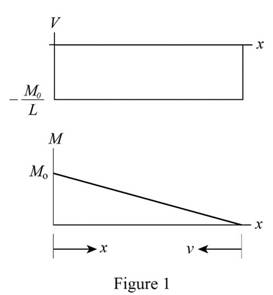
Refer to Figure 1.
Maximum shear force V=−M0L.
Maximum bending moment Mmax=M0.
Bending moment at a distance v from B M=M0Lv
Calculate the strain energy due to bending (U1) as shown below.
U1=∫baM22EIdv
Substitute M=M0Lv for M and apply the limits.
U1=∫L0(M0Lv)22EIdv=12EI∫L0M20v2L2dv=M202EIL2(v33)L0=M206EIL2×L3
=M20L6EI
Substitute bd312 for I.
U1=M20L6E(bd312)=2M20Lbd3E
Calculate the shear stress (τxy) as shown below.
τxy=32VA(1−y2c2)
Calculate the strain energy density (u) as shown below.
u=τ2xy2G
Here, G is the modulus of rigidity.
Substitute 32VA(1−y2c2) for τxy.
u=(32VA(1−y2c2))22G=9V28GA2(1+y4c4−2y2c2)
Substitute bd for A.
u=9V28G(bd)2(1+y4c4−2y2c2)=9V28Gb2d2(1+y4c4−2y2c2)
The value of v=bdy.
Differentiate both sides of the Equation as shown below.
dv=bdy dx
Calculate the strain energy due to shear as shown below.
U2=∫u dv
Substitute 9V28Gb2d2(1+y4c4−2y2c2) for u, bdy dx for dv, and apply the limits.
U2=L∫0∫c−c9V28Gb2d2(1+y4c4−2y2c2)bdy dx=9V28Gbd2L∫0∫c−c(1+y4c4−2y2c2)dy dx=9V28Gbd2L∫0(y+y55c4−2y33c2)c−cdx=9V28Gbd2{(c+c55c4−2c33c2)−((−c)+(−c)55c4−2(−c)33c2)}(x)L0
=9V28Gbd2{c+c5−2c3+c+c5−2c3}L=9V2cL8Gbd2×(15+3−10+15+3−10)15=9V2cL8Gbd2×1615=6V2cL5Gbd2
Substitute −M0L for V and d2 for c.
U2=6(−M0L)2(d2)L5Gbd2=3M205GbdL
Calculate the total strain energy as shown below.
U=U1+U2
Substitute 2M20Lbd3E for U1 and 3M205GbdL for U2.
U=2M20Lbd3E+3M205GbdL=2M20LEbd3(1+3Ed210GL2)
Hence, the strain energy of the prismatic beam AB is U=2M20LEbd3{1+3Ed210GL2}_.
Want to see more full solutions like this?
Chapter 11 Solutions
Mechanics of Materials, 7th Edition


- A 3-in.-radius drum is rigidly attached to a 5-in.-radius drum as shown. One of the drums rolls without sliding on the surface shown, and a cord is wound around the other drum. Knowing that at the instant shown. point A has a velocity of 4.875 in./sin./s and an acceleration of 15.50 in./s2in./s2 , both directed to the right, determine the accelerations of points A, B, and C of the drums. The cord is wound around the 3 inch radius drum. Point B is at the bottom of the 5 inch radius drum. Point A is at the bottom of the 3 inch radius drum. Point C is on the right edge of the 5 inch radius drum. The accelerations of point B is ______ in./s2 The accelerations of point A is ______ in./s2 _____⦨ °. The accelerations of point C is _______ in./s2 ____ ⦪ °.arrow_forwardThe average heat transfer coefficent for airflow over an odd shaped body is to be determined by mass transfer measurements and using the Chilton-Colburn analogy btwn heat and mass transfer. The experiemnt is conducted by blowing dry air at 1 atm at a free-stream velocity of 2 m/s over a body covered with a layer of naphthalene. The surface area of the body is .75 m^2, and it is observed that 100 g of maphthalene has sublimated in 45 min. During the experiemnt, both the body and the air were kep at 25oC, at which the vapor pressure and mass diffusivity of naphthalene are 11 Pa and Dab=0.61*10^-5 m^2/s respectively. Determine the heat transfer coefficent under the same flow conditions over the same geometry.arrow_forwardAuto Controls Design a PID controller for thefollowing system so that the modified system satisfies the followingspecifications : 1. settling time ,ts = 1.96 s and % Overshoot Mp = 70.7 % Assume a non-dominant pole at s = -15 to solve the problem The plot the compensated andThen plot the uncompensated system in MATLAB. what can you see from the plot ? what is your observation ?arrow_forward
- Auto Controls The figure is a schematic diagram of an aircraft elevator control system. The input to the systemin the deflection angle of the control lever , and the output is the elevator angle phi.show that for each angle theta of the control lever ,there is a corresponding elevator angle phi. Then find Y(s)/theta(s) and simplify the resulting transfer function . Also note from the diagram that y and phi is relatedarrow_forwardFresh water is planned to be pumped in a certain pipe at constant pumping rate of 6.5 gpm. If water density and viscosity are 8.34 ppg and 1.0 cp, what is the minimum pipe inside diameter that make the fluid flow behave as turbulent flow?arrow_forwardUSE MATLAB ONLY provide typed code Turbomachienery . GIven: vx = 185 m/s, flow angle = 60 degrees, R = 0.5, U = 150 m/s, b2 = -a3, a2 = -b3 Find: velocity triangle , a. magnitude of abs vel leaving rotor (m/s) b. flow absolute angles (a1, a2, a3) 3. flow rel angles (b2, b3) d. specific work done e. use code to draw vel. diagram Use this code for plot % plots Velocity Tri. in Ch4 function plotveltri(al1,al2,al3,b2,b3) S1L = [0 1]; V1x = [0 0]; V1s = [0 1*tand(al3)]; S2L = [2 3]; V2x = [0 0]; V2s = [0 1*tand(al2)]; W2s = [0 1*tand(b2)]; U2x = [3 3]; U2y = [1*tand(b2) 1*tand(al2)]; S3L = [4 5]; V3x = [0 0]; V3r = [0 1*tand(al3)]; W3r = [0 1*tand(b3)]; U3x = [5 5]; U3y = [1*tand(b3) 1*tand(al3)]; plot(S1L,V1x,'k',S1L,V1s,'r',... S2L,V2x,'k',S2L,V2s,'r',S2L,W2s,'b',U2x,U2y,'g',... S3L,V3x,'k',S3L,V3r,'r',S3L,W3r,'b',U3x,U3y,'g',...... 'LineWidth',2,'MarkerSize',10),... axis([-1 6 -4 4]), ... title('Velocity Triangle'), ... xlabel('x'),ylarrow_forward
- Consider a 12 cm internal diameter, 14 m long circular duct whose interior surface is wet. The duct is to be dried by forcing dry air at 1 atm and 15oC throught it at an average velocity of 3m/s. The duct passes through a chilled roo, and it remains at an average temp of 15oC at all time. Determine the mass transfer coeeficient in the duct.arrow_forwardConsider a 5m by 5m wet concret patio with an average water film thickness of .2mm. Now wind at 50 km/h is blowing over the surface. If the air is at 1 atm, 15oC and 35 percent relative humidity, determine how long it will take for the patio to completely dry.arrow_forwardA double thread worm gear has a pitch of 1 1/8 and a pitch diameter of 3 in. It has a coefficient of friction of 0.20 and normal angle (pressure angle) of 14.5o. The worm is supplied by 12 hp at 1200 rpm motor. Find the tangential force on the gear. The worm is left hand threads.arrow_forward
- A double thread worm gear has a pitch of 1 1/8 and a pitch diameter of 3 in. It has a coefficient of friction of 0.20 and normal angle (pressure angle) of 14.5o. The worm is supplied by 12 hp at 1200 rpm motor. Find the tangential force on the gear. The worm is left hand threads.arrow_forwardA 2 mm thick, 5L vessel made of nickel is used ot store hydrogen gas at 358 K and 300 kPa. If the total inner surface area of the vessel is 1600 cm^2, determine the rate of gas loss from the nickel vessel via mas diffusion. Also, determine the fraction of the hydrogen lost by mass diffusion after one year of storage.arrow_forward< 7:19 The 1st homework 6. Multiple Choice a)唧筒机构 5G31 Which of followings can be th e kinematic diagram of this mechanism? A B Darrow_forward
 Elements Of ElectromagneticsMechanical EngineeringISBN:9780190698614Author:Sadiku, Matthew N. O.Publisher:Oxford University Press
 Mechanics of Materials (10th Edition)Mechanical EngineeringISBN:9780134319650Author:Russell C. HibbelerPublisher:PEARSON
 Thermodynamics: An Engineering ApproachMechanical EngineeringISBN:9781259822674Author:Yunus A. Cengel Dr., Michael A. BolesPublisher:McGraw-Hill Education
 Control Systems EngineeringMechanical EngineeringISBN:9781118170519Author:Norman S. NisePublisher:WILEY
 Mechanics of Materials (MindTap Course List)Mechanical EngineeringISBN:9781337093347Author:Barry J. Goodno, James M. GerePublisher:Cengage Learning
 Engineering Mechanics: StaticsMechanical EngineeringISBN:9781118807330Author:James L. Meriam, L. G. Kraige, J. N. BoltonPublisher:WILEY