
Mechanics of Materials, 7th Edition
7th Edition
ISBN: 9780073398235
Author: Ferdinand P. Beer, E. Russell Johnston Jr., John T. DeWolf, David F. Mazurek
Publisher: McGraw-Hill Education
expand_more
expand_more
format_list_bulleted
Videos
Textbook Question
Chapter 11.3, Problem 38P
The state of stress shown occurs in a machine component made of a grade of steel for which σY = 65 ksi. Using the maximum-distortion-energy criterion, determine the range of values of σy for which the factor of safety associated with the yield strength is equal to or larger than 2.2.
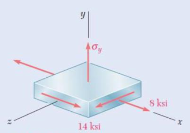
Fig. P11.38 and P11.39
Expert Solution & Answer
Want to see the full answer?
Check out a sample textbook solution
Students have asked these similar questions
28. A 300 mm rod is subjected to 4 kN of tensile force. The allowable stress and deformation is 60 MPa and
0.05 mm. Determine the required diameter of the rod in mm. Use E = 200 GPa.
9.5
b. 10.5
а.
с.
11.5
d. 12.5
11.9 (A/B). Develop from first principles an expression for the instantaneous stress set up in a vertical bar by a
weight W falling from a height h on to a stop at the end of the bar. The instantaneous extension x may not be
neglected.
A weight of 500 N can slide freely on a vertical steel rod 2.5 m long and 20 mm diameter. The rod is rigidly fixed at
its upper end and has a collar at the lower end to prevent the weight from dropping off. The weight is lifted to a
distance of 50 mm above the collar and then released. Find the maximum instantaneous stress produced in the rod.
E = 200 GN/m³.
[114 MN/m²]
12. A single strain gage is cemented to
solid 96-mm-diameter aluminum
shaft at an angle B = 20° with a line
parallel to the axis of the shaft.
Knowing that G = 27 GPa, determine
the torque T corresponding to a gage
reading of 400u.
48 mm
Figure P12
Chapter 11 Solutions
Mechanics of Materials, 7th Edition
Ch. 11.3 - Determine the modulus of resilience for each of...Ch. 11.3 - Determine the modulus of resilience for each of...Ch. 11.3 - Determine the modulus of resilience for each of...Ch. 11.3 - Determine the modulus of resilience for each of...Ch. 11.3 - The stress-strain diagram shown has been drawn...Ch. 11.3 - The stress-strain diagram shown has been drawn...Ch. 11.3 - Prob. 7PCh. 11.3 - Prob. 8PCh. 11.3 - Using E = 29 106 psi, determine (a) the strain...Ch. 11.3 - Using E = 200 GPa, determine (a) the strain energy...
Ch. 11.3 - A 30-in. length of aluminum pipe of...Ch. 11.3 - A single 6-mm-diameter steel pin B is used to...Ch. 11.3 - Prob. 13PCh. 11.3 - Prob. 14PCh. 11.3 - The assembly ABC is made of a steel for which E =...Ch. 11.3 - Show by integration that the strain energy of the...Ch. 11.3 - Prob. 17PCh. 11.3 - Prob. 18PCh. 11.3 - Prob. 19PCh. 11.3 - 11.18 through 11.21 In the truss shown, all...Ch. 11.3 - Prob. 21PCh. 11.3 - Each member of the truss shown is made of aluminum...Ch. 11.3 - Each member of the truss shown is made of aluminum...Ch. 11.3 - 11.24 through 11.27 Taking into account only the...Ch. 11.3 - Prob. 25PCh. 11.3 - 11.24 through 11.27 Taking into account only the...Ch. 11.3 - 11.24 through 11.27 Taking into account only the...Ch. 11.3 - Prob. 28PCh. 11.3 - Prob. 29PCh. 11.3 - Prob. 30PCh. 11.3 - 11.30 and 11.31 Using E = 200 GPa, determine the...Ch. 11.3 - Assuming that the prismatic beam AB has a...Ch. 11.3 - Prob. 33PCh. 11.3 - The design specifications for the steel shaft AB...Ch. 11.3 - Show by integration that the strain energy in the...Ch. 11.3 - The state of stress shown occurs in a machine...Ch. 11.3 - Prob. 37PCh. 11.3 - The state of stress shown occurs in a machine...Ch. 11.3 - Prob. 39PCh. 11.3 - Prob. 40PCh. 11.3 - Prob. 41PCh. 11.5 - A 5-kg collar D moves along the uniform rod AB and...Ch. 11.5 - The 18-lb cylindrical block E has a horizontal...Ch. 11.5 - The cylindrical block E has a speed v0 =16 ft/s...Ch. 11.5 - Prob. 45PCh. 11.5 - Prob. 46PCh. 11.5 - The 48-kg collar G is released from rest in the...Ch. 11.5 - Prob. 48PCh. 11.5 - Prob. 49PCh. 11.5 - Prob. 50PCh. 11.5 - Prob. 51PCh. 11.5 - The 2-kg block D is dropped from the position...Ch. 11.5 - The 10-kg block D is dropped from a height h = 450...Ch. 11.5 - Prob. 54PCh. 11.5 - A 160-lb diver jumps from a height of 20 in. onto...Ch. 11.5 - Prob. 56PCh. 11.5 - A block of weight W is dropped from a height h...Ch. 11.5 - 11.58 and 11.59 Using the method of work and...Ch. 11.5 - 11.58 and 11.59 Using the method of work and...Ch. 11.5 - 11.60 and 11.61 Using the method of work and...Ch. 11.5 - 11.60 and 11.61 Using the method of work and...Ch. 11.5 - 11.62 and 11.63 Using the method of work and...Ch. 11.5 - 11.62 and 11.63 Using the method of work and...Ch. 11.5 - Using the method of work and energy, determine the...Ch. 11.5 - Using the method of work and energy, determine the...Ch. 11.5 - The 20-mm diameter steel rod BC is attached to the...Ch. 11.5 - Torques of the same magnitude T are applied to the...Ch. 11.5 - Prob. 68PCh. 11.5 - The 20-mm-diameter steel rod CD is welded to the...Ch. 11.5 - The thin-walled hollow cylindrical member AB has a...Ch. 11.5 - 11.71 and 11.72 Each member of the truss shown has...Ch. 11.5 - 11.71 and 11.72 Each member of the truss shown has...Ch. 11.5 - Each member of the truss shown is made of steel...Ch. 11.5 - Each member of the truss shown is made of steel....Ch. 11.5 - Each member of the truss shown is made of steel...Ch. 11.5 - The steel rod BC has a 24-mm diameter and the...Ch. 11.9 - 11.77 and 11.78 Using the information in Appendix...Ch. 11.9 - 11.77 and 11.78 Using the information in Appendix...Ch. 11.9 - 11.79 through 11.82 For the beam and loading...Ch. 11.9 - 11.79 through 11.82 For the beam and loading...Ch. 11.9 - 11.79 through 11.82 For the beam and loading...Ch. 11.9 - 11.79 through 11.82 For the beam and loading...Ch. 11.9 - 11.83 through 11.85 For the prismatic beam shown,...Ch. 11.9 - 11.83 through 11.85 For the prismatic beam shown,...Ch. 11.9 - 11.83 through 11.85 For the prismatic beam shown,...Ch. 11.9 - 11.86 through 11.88 For the prismatic beam shown,...Ch. 11.9 - 11.86 through 11.88 For the prismatic beam shown,...Ch. 11.9 - 11.86 through 11.88 For the prismatic beam shown,...Ch. 11.9 - For the prismatic beam shown, determine the slope...Ch. 11.9 - For the prismatic beam shown, determine the slope...Ch. 11.9 - For the beam and loading shown, determine the...Ch. 11.9 - For the beam and loading shown, determine the...Ch. 11.9 - 11.93 and 11.94 For the beam and loading shown,...Ch. 11.9 - 11.93 and 11.94 For the beam and loading shown,...Ch. 11.9 - For the beam and loading shown, determine the...Ch. 11.9 - For the beam and loading shown, determine the...Ch. 11.9 - Prob. 97PCh. 11.9 - For the beam and loading shown, determine the...Ch. 11.9 - 11.99 and 11.100 For the truss and loading shown,...Ch. 11.9 - 11.99 and 11.100 For the truss and loading shown,...Ch. 11.9 - 11.101 and 11.102 Each member of the truss shown...Ch. 11.9 - 11.101 and 11.102 Each member of the truss shown...Ch. 11.9 - 11.103 and 11.104 Each member of the truss shown...Ch. 11.9 - 11.103 and 11 104 Each member of the truss shown...Ch. 11.9 - A uniform rod of flexural rigidity EI is bent and...Ch. 11.9 - For the uniform rod and loading shown and using...Ch. 11.9 - For the beam and loading shown and using...Ch. 11.9 - Two rods AB and BC of the same flexural rigidity...Ch. 11.9 - Three rods, each of the same flexural rigidity EI,...Ch. 11.9 - Three rods, each of the same flexural rigidity EI,...Ch. 11.9 - 11.111 through 11.115 Determine the reaction at...Ch. 11.9 - 11.111 through 11.115 Determine the reaction at...Ch. 11.9 - 11.111 through 11.115 Determine the reaction at...Ch. 11.9 - 11.111 through 11.115 Determine the reaction at...Ch. 11.9 - 11.111 through 11.115 Determine the reaction at...Ch. 11.9 - For the uniform beam and loading shown, determine...Ch. 11.9 - 11.117 through 11.120 Three members of the same...Ch. 11.9 - 11.117 through 11.120 Three members of the same...Ch. 11.9 - 11.117 through 11.120 Three members of the same...Ch. 11.9 - 11.117 through 11.120 Three members of the same...Ch. 11.9 - 11.121 and 11.122 Knowing that the eight members...Ch. 11.9 - 11.121 and 11.122 Knowing that the eight members...Ch. 11 - Rod AB is made of a steel for which the yield...Ch. 11 - Each member of the truss shown is made of steel...Ch. 11 - The ship at A has just started to drill for oil on...Ch. 11 - Collar D is released from rest in the position...Ch. 11 - Each member of the truss shown is made of steel...Ch. 11 - A block of weight W is placed in contact with a...Ch. 11 - Two solid steel shafts are connected by the gears...Ch. 11 - A 160-lb diver jumps from a height of 20 in. onto...Ch. 11 - For the prismatic beam shown, determine the slope...Ch. 11 - A disk of radius a has been welded to end B of the...Ch. 11 - A uniform rod of flexural rigidity EI is bent and...Ch. 11 - The steel bar ABC has a square cross section of...
Knowledge Booster


Learn more about
Need a deep-dive on the concept behind this application? Look no further. Learn more about this topic, mechanical-engineering and related others by exploring similar questions and additional content below.Similar questions
- For the structure shown, design the maximum permissible value of W using a factor of safety of 2, based on the following conditions. a. Ultimate normal stress in members CD and EF is 140 ksi. b. Ultimate shear stress in pins B, D, F, and H is 100 ksi. c. Ultimate bearing stress on member ACEG is 200 ksi. d. Ultimate bearing stress on support plates at B and H is 240 ksi. All members have dimensions of 5 x 2 in while the support plates have 1.5 in. thickness. Pins at B and H have 1 in. diameter while pins C, E, D, and F have 3/4 in. diameter. Note that there are two identical members CD and two identical members EF. Also, there are two support plates in B while only one plate is used in H. W A B 13 ft- 3 3 10 ft- 4 ft -3 ft-arrow_forwardFig. 1 45° «НШЕННННННА QUESTION 1 The 50-kg flowerpot in Fig. 1 is suspended from wires AB and BC. If the wires have a normal failure stress of ofail = 350 MPa, determine the minimum diameter of each wire. Use a factor of safety of 2.5. QUESTION 2 The 50-kg flowerpot in Fig. 1 is suspended from wires AB and BC which have diameters of 1.5 mm and 2 mm, respectively. If the wires have a normal failure stress of fail = 350 MPa, determine the factor of safety of each wire.arrow_forward12 ksi Txy 3 ksi Fig. P7.83arrow_forward
- Two gage marks are placed exactly 10 in. apart on a 1⁄2-in.-diameter aluminum rod with E = 10.1 x 10⁶ psi and an ultimate strength of 16 ksi. Knowing that the distance between the gage marks is 10.009 in. after a load isapplied, determine (a) the stress in the rod, (b) the factor of safety, (c) the corresponding normal stress in thewire.arrow_forwardKnowing that a 0.02in gap exists when the temperature is 75°F, determine (a) the temperature at which the normal stress in the aluminum bar will be equal to -11ksi, (b) the corresponding exact length (2 decimal places in 10-3 inches) of the aluminum bar. 0.02 in. 14 in. Bronze A = 2.4 in² E = 15 × 106 psi α = 12 × 10-6/°F NOTE: ANSWER ITEM (b) 18.01 18 in. Aluminum A = 2.8 in² E = 10.6 × 10⁶ psi a = 12.9 × 10⁻⁶/°Farrow_forwardDetermine the values of the stress in portions AC and CB of the steel bar shown Fig. when the temperature of the bar is 2508F, knowing that a close fit exists at both of the rigid supports when the temperature is 1758F. Use the values E=29 *106 psi and α=6.5 * 10–6/8F for steelarrow_forward
- Two gage marks are placed exactly 250mm apart on a 12mm-diameter aluminum rod with E=73Gpa and an ultimate strength of 140Mpa. Knowing that the distance between the gage marks is 250.28mm after a load is applied, determine (a) the stress in the rod, (b) the factor of safety.arrow_forwardIn a standard tensile test, a steel rod of 22-mm diameter is subjected to a tension force of 75 kN. Knowing that ν=0.30 and E=200 GPa, determine (a) the elongation of the rod in a 200-mm gage length, (b) the change in diameter of the rodarrow_forwardA 12-kN tensile load will be applied to a 50-m length of steel wire with E= 200 GPa. Determine the smallest diameter wire that can be used, knowing that the normal stress must not exceed 150 MPa and that the increase in length of the wire must not exceed 25 mm. The smallest diameter that can be used is mm.arrow_forward
- A steel wire 30 ft long, hanging vertically, supports a load of 500 lb. Neglecting the weight of the wire, determine the required diameter if the stress is not to exceed 20 ksi and the total elongation is not to exceed 0.10 in. Assume E = 29 × 10° psi. 0.22 in 0.30 in 0.28 in. 0.20 in.arrow_forward* 1. A cantilever machine component, of solid circular cross section with a diameter d and a length of 60 cm, is to be fabricated of an iron-base alloy for which the endurance limit is 360 MPa. The component is to be subjected at the free end to a completely reversed loading of 8800 N maximum value. Ignore stress concentrations and use a factor of safety of 3 to determine the required diameter of the member.arrow_forwardThe maximum gage pressure is known to be 1150 psi in a spherical steel pressure vessel having a 10-in. outer diameter and a 0.25-in. wall thickness. Knowing that the ultimate stress in the steel used is σU=60 ksi, determine the factor of safety with respect to tensile failure.arrow_forward
arrow_back_ios
SEE MORE QUESTIONS
arrow_forward_ios
Recommended textbooks for you
 Elements Of ElectromagneticsMechanical EngineeringISBN:9780190698614Author:Sadiku, Matthew N. O.Publisher:Oxford University Press
 Mechanics of Materials (10th Edition)Mechanical EngineeringISBN:9780134319650Author:Russell C. HibbelerPublisher:PEARSON
 Thermodynamics: An Engineering ApproachMechanical EngineeringISBN:9781259822674Author:Yunus A. Cengel Dr., Michael A. BolesPublisher:McGraw-Hill Education
 Control Systems EngineeringMechanical EngineeringISBN:9781118170519Author:Norman S. NisePublisher:WILEY
 Mechanics of Materials (MindTap Course List)Mechanical EngineeringISBN:9781337093347Author:Barry J. Goodno, James M. GerePublisher:Cengage Learning
 Engineering Mechanics: StaticsMechanical EngineeringISBN:9781118807330Author:James L. Meriam, L. G. Kraige, J. N. BoltonPublisher:WILEY
Elements Of Electromagnetics
Mechanical Engineering
ISBN:9780190698614
Author:Sadiku, Matthew N. O.
Publisher:Oxford University Press
Mechanics of Materials (10th Edition)
Mechanical Engineering
ISBN:9780134319650
Author:Russell C. Hibbeler
Publisher:PEARSON
Thermodynamics: An Engineering Approach
Mechanical Engineering
ISBN:9781259822674
Author:Yunus A. Cengel Dr., Michael A. Boles
Publisher:McGraw-Hill Education
Control Systems Engineering
Mechanical Engineering
ISBN:9781118170519
Author:Norman S. Nise
Publisher:WILEY
Mechanics of Materials (MindTap Course List)
Mechanical Engineering
ISBN:9781337093347
Author:Barry J. Goodno, James M. Gere
Publisher:Cengage Learning
Engineering Mechanics: Statics
Mechanical Engineering
ISBN:9781118807330
Author:James L. Meriam, L. G. Kraige, J. N. Bolton
Publisher:WILEY
Mechanical SPRING DESIGN Strategy and Restrictions in Under 15 Minutes!; Author: Less Boring Lectures;https://www.youtube.com/watch?v=dsWQrzfQt3s;License: Standard Youtube License