
Statics and Mechanics of Materials (5th Edition)
5th Edition
ISBN: 9780134382593
Author: Russell C. Hibbeler
Publisher: PEARSON
expand_more
expand_more
format_list_bulleted
Concept explainers
Videos
Textbook Question
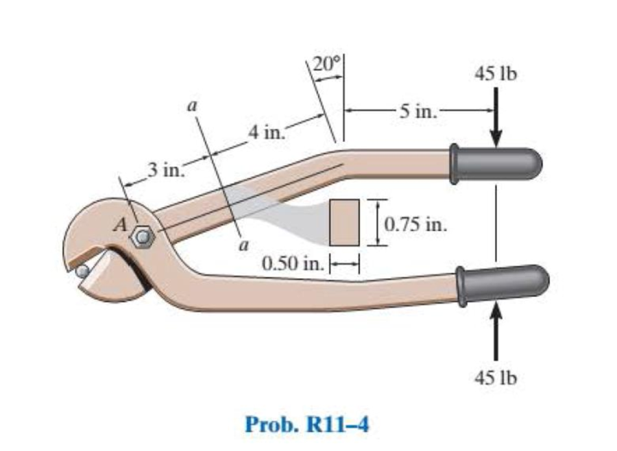
Chapter 11, Problem 4RP
Determine the maximum bending stress in the handle of the cable cutter at section a–a. A force of 45 lb is applied to the handles.
Expert Solution & Answer
Want to see the full answer?
Check out a sample textbook solution
Students have asked these similar questions
If the maximum bending stress at section a–a is not allowed to exceed sallow= 150 MPa, determine the maximum allowable force P that can be applied to the end E.
Determine the internal normal force, shear force, and bending moment at points D and E of the bell crank that is pinned at A and supported by a short link BC.
Determine the absolute maximum bending stress in the 80-mm-diameter shaft which is subjected to the concentrated forces. There is a journal bearing at A and a thrust bearing at B.
Chapter 11 Solutions
Statics and Mechanics of Materials (5th Edition)
Ch. 11.2 - In each case, the beam is subjected to the...Ch. 11.2 - In each ease, express the shear and moment...Ch. 11.2 - In each ease, express the shear and moment...Ch. 11.2 - In each ease, express the shear and moment...Ch. 11.2 - In each ease, express the shear and moment...Ch. 11.2 - Prob. 5FPCh. 11.2 - Prob. 6FPCh. 11.2 - In each ease, draw the shear and moment diagrams...Ch. 11.2 - Prob. 8FPCh. 11.2 - Prob. 1P
Ch. 11.2 - Draw the shear and moment diagrams for the beam,...Ch. 11.2 - Draw the shear and moment diagrams for the beam,...Ch. 11.2 - Express the shear and moment in terms of x for 0 ...Ch. 11.2 - Express the internal shear and moment in the...Ch. 11.2 - Prob. 6PCh. 11.2 - Express the internal shear and moment in terms of...Ch. 11.2 - Draw the shear and moment diagrams for the beam,...Ch. 11.2 - If the force applied to the handle of the load...Ch. 11.2 - Draw the shear and moment diagrams for the shaft....Ch. 11.2 - The crane is used to support the engine, which has...Ch. 11.2 - Prob. 12PCh. 11.2 - Draw the shear and moment diagrams for the beam....Ch. 11.2 - Draw the shear and moment diagrams for the beam....Ch. 11.2 - Members ABC and BD of the counter chair are...Ch. 11.2 - A reinforced concrete pier is used to support the...Ch. 11.2 - Draw the shear and moment diagrams for the beam...Ch. 11.2 - The industrial robot is held in the stationary...Ch. 11.2 - Determine the placement distance a of the roller...Ch. 11.2 - Prob. 20PCh. 11.2 - Draw the shear and moment diagrams for the beam....Ch. 11.2 - Draw the shear and moment diagrams for the...Ch. 11.2 - The 150-lb man sits in the center of the boat,...Ch. 11.2 - Prob. 24PCh. 11.2 - The footing supports the load transmitted by the...Ch. 11.2 - Prob. 26PCh. 11.2 - Prob. 27PCh. 11.2 - Draw the shear and moment diagrams for the beam....Ch. 11.2 - Draw the shear and moment diagrams for the beam....Ch. 11.2 - Prob. 30PCh. 11.2 - Prob. 31PCh. 11.2 - Prob. 32PCh. 11.2 - The shaft is supported by a smooth thrust bearing...Ch. 11.2 - Draw the shear and moment diagrams for the...Ch. 11.2 - Draw the shear and moment diagrams for the beam....Ch. 11.2 - Draw the shear and moment diagrams for the rod....Ch. 11.2 - Draw the shear and moment diagrams for the beam....Ch. 11.2 - Prob. 38PCh. 11.2 - Draw the shear and moment diagrams for the double...Ch. 11.2 - Draw the shear and moment diagrams for the simply...Ch. 11.2 - The compound beam is fixed at A, pin connected at...Ch. 11.2 - Draw the shear and moment diagrams for the...Ch. 11.2 - The compound beam is fixed at A, pin connected at...Ch. 11.2 - Draw the shear and moment diagrams for the beam....Ch. 11.2 - A short link at B is used to connect beams AB and...Ch. 11.2 - The truck is to be used to transport the concrete...Ch. 11.4 - Determine the moment of inertia of the cross...Ch. 11.4 - Prob. 3PPCh. 11.4 - In each case, show how the bending stress acts on...Ch. 11.4 - Prob. 5PPCh. 11.4 - If the beam is subjected to a bending moment of M...Ch. 11.4 - If the beam is subjected to a bending moment of M...Ch. 11.4 - If the beam is subjected to a bending moment of M...Ch. 11.4 - Prob. 12FPCh. 11.4 - If the beam is subjected to a bending moment of M...Ch. 11.4 - An A-36 steel strip has an allowable bending...Ch. 11.4 - Determine the moment M that will produce a maximum...Ch. 11.4 - Determine the maximum tensile and compressive...Ch. 11.4 - The beam is constructed from four pieces of wood,...Ch. 11.4 - The beam is constructed from four pieces of wood,...Ch. 11.4 - The beam is made from three boards nailed together...Ch. 11.4 - Prob. 53PCh. 11.4 - If the built-up beam is subjected to an internal...Ch. 11.4 - If the built-up beam is subjected to an internal...Ch. 11.4 - Prob. 56PCh. 11.4 - Determine the moment M that should be applied to...Ch. 11.4 - Prob. 58PCh. 11.4 - Prob. 59PCh. 11.4 - The beam is subjected to a moment of 15 kip ft....Ch. 11.4 - The beam is subjected to a moment of 15 kip ft....Ch. 11.4 - Prob. 62PCh. 11.4 - The steel shaft has a diameter of 2 in. It is...Ch. 11.4 - The beam is made of steel that has an allowable...Ch. 11.4 - Prob. 65PCh. 11.4 - Solve Prob. 11-65 if the moment M = 50 N m is...Ch. 11.4 - The shaft is supported by smooth journal bearings...Ch. 11.4 - Prob. 68PCh. 11.4 - Prob. 69PCh. 11.4 - The strut on the utility pole supports the cable...Ch. 11.4 - Prob. 71PCh. 11.4 - Prob. 72PCh. 11.4 - Determine the smallest allowable diameter of the...Ch. 11.4 - Prob. 74PCh. 11.4 - The shaft is supported by a thrust bearing at A...Ch. 11.4 - If the intensity of the load w = 15 kN/m,...Ch. 11.4 - If the allowable bending stress is allow = 150...Ch. 11.4 - The beam is subjected to the triangular...Ch. 11.4 - The beam has a rectangular cross section with b =...Ch. 11.4 - Determine the absolute maximum bending stress in...Ch. 11.4 - If the compound beam in Prob. 11-42 has a square...Ch. 11.4 - Prob. 82PCh. 11.4 - Prob. 83PCh. 11.4 - Determine, to the nearest millimeter, the smallest...Ch. 11.4 - Prob. 85PCh. 11.4 - Determine the absolute maximum bending stress in...Ch. 11.4 - Determine the smallest diameter of the shaft to...Ch. 11.4 - Prob. 88PCh. 11.4 - A log that is 2 ft in diameter is to be cut into a...Ch. 11.4 - The simply supported truss is subjected to the...Ch. 11.4 - Prob. 92PCh. 11.4 - Prob. 93PCh. 11.4 - Prob. 94PCh. 11.4 - The beam has the rectangular cross section shown....Ch. 11.5 - Determine the bending stress developed at corners...Ch. 11.5 - Prob. 15FPCh. 11.5 - Prob. 96PCh. 11.5 - Prob. 97PCh. 11.5 - Prob. 98PCh. 11.5 - Prob. 99PCh. 11.5 - Determine the bending stress at point A of the...Ch. 11.5 - The steel shaft is subjected to the two loads. If...Ch. 11.5 - Prob. 102PCh. 11.5 - Prob. 103PCh. 11.5 - Prob. 104PCh. 11 - Determine the shape factor for the wide-flange...Ch. 11 - The compound beam consists of two segments that...Ch. 11 - A shaft is made of a polymer having a parabolic...Ch. 11 - Determine the maximum bending stress in the handle...Ch. 11 - Determine the shear and moment in the beam as...Ch. 11 - A wooden beam has a square cross section as shown....Ch. 11 - Prob. 7RPCh. 11 - The strut has a square cross section a by a and is...
Knowledge Booster


Learn more about
Need a deep-dive on the concept behind this application? Look no further. Learn more about this topic, mechanical-engineering and related others by exploring similar questions and additional content below.Similar questions
- RII-I. The chair is supported by an arm that is hinged so it rotates about the vertical axis at A. If the load on the chair is 900 N and the arm is a holkow tube section having the dimensions shown, determine the maximum bending stress at section a-a. 900 N 25 mm 75 mm 63 mm Fa00 HFmmarrow_forwardThe beam is to be used to support the machine, which exerts the forces of 6 kip and 8 kip. If the maximum bending stress is not to exceed sallow = 22 ksi, determine the required width b of the flanges.arrow_forwardThe bar has a thickness of 0.5 in. and is subjected to a moment of 600 lb # ft. Determine the maximum bending stress in the bar.arrow_forward
- The handle of the press is subjected to a force of 20 lb. Due to internal gearing, this causes the block to be subjected to a compressive force of 80 lb. Determine the normal-stress acting in the frame at points along the outside flanges A and B. Use the curved-beam formula to calculate the bending stress.arrow_forwardThe pin is used to connect the three links together. Due to wear, the load is distributed over the top and bottom of the pin as shown on the free-body diagram. If the diameter of the pin is 0.40 in., determine the maximum bending stress on the cross-sectional area at the center section a–a. For the solution it is first necessary to determine the load intensities w1 and w2.arrow_forwardDetermine the internal normal force at point C, if F = 48 kN . Determine the shear force at point C Determine the bending moment at point Carrow_forward
- Determine the shear stress at point B on the web of the cantilevered strut at section a–a.arrow_forwardAn A-36 steel strap having a thickness of 10 mm and a width of 20 mm is bent into a circular arc of radius r = 10 m. Determine the maximum bending stress in the strap.arrow_forwardIn each case, determine the largest internal shear force resisted by the bolt. Include all necessary free-body diagrams.arrow_forward
- Determine the internal normal force, shear force, and moment at points D and E in the compound beam. Point E is located just to the left of the 10kN concentrated load. Assume the support at A is fixed and the connection at B is a pin. 2 kN/m D E -1.5 m 1.5 m 1.5 m----1.5m- --- 10 KN --arrow_forwardIf P = 3 kN, determine the bending stress at points A, B, and C of the cross section at section a–a. Using these results, sketch the stress distribution on section a–a.arrow_forwardThe stepped bar has a thickness of 15 mm. Determine the maximum moment that can be applied to its ends if it is made of a material having an allowable bending stress of 200 MPa. 45 mm 30 mm 3 mm 10 mm 6 mm Marrow_forward
arrow_back_ios
SEE MORE QUESTIONS
arrow_forward_ios
Recommended textbooks for you
 Elements Of ElectromagneticsMechanical EngineeringISBN:9780190698614Author:Sadiku, Matthew N. O.Publisher:Oxford University Press
 Mechanics of Materials (10th Edition)Mechanical EngineeringISBN:9780134319650Author:Russell C. HibbelerPublisher:PEARSON
 Thermodynamics: An Engineering ApproachMechanical EngineeringISBN:9781259822674Author:Yunus A. Cengel Dr., Michael A. BolesPublisher:McGraw-Hill Education
 Control Systems EngineeringMechanical EngineeringISBN:9781118170519Author:Norman S. NisePublisher:WILEY
 Mechanics of Materials (MindTap Course List)Mechanical EngineeringISBN:9781337093347Author:Barry J. Goodno, James M. GerePublisher:Cengage Learning
 Engineering Mechanics: StaticsMechanical EngineeringISBN:9781118807330Author:James L. Meriam, L. G. Kraige, J. N. BoltonPublisher:WILEY
Elements Of Electromagnetics
Mechanical Engineering
ISBN:9780190698614
Author:Sadiku, Matthew N. O.
Publisher:Oxford University Press
Mechanics of Materials (10th Edition)
Mechanical Engineering
ISBN:9780134319650
Author:Russell C. Hibbeler
Publisher:PEARSON
Thermodynamics: An Engineering Approach
Mechanical Engineering
ISBN:9781259822674
Author:Yunus A. Cengel Dr., Michael A. Boles
Publisher:McGraw-Hill Education
Control Systems Engineering
Mechanical Engineering
ISBN:9781118170519
Author:Norman S. Nise
Publisher:WILEY
Mechanics of Materials (MindTap Course List)
Mechanical Engineering
ISBN:9781337093347
Author:Barry J. Goodno, James M. Gere
Publisher:Cengage Learning
Engineering Mechanics: Statics
Mechanical Engineering
ISBN:9781118807330
Author:James L. Meriam, L. G. Kraige, J. N. Bolton
Publisher:WILEY
The Most Common Metal Machining Processes (Metal Machining Video 1); Author: Sofeast Ltd;https://www.youtube.com/watch?v=uxVJ3qtezGw;License: Standard YouTube License, CC-BY
Machining process and Machine Tools; Author: Amar Gandhi;https://www.youtube.com/watch?v=X2mUJ8baaE0;License: Standard Youtube License