
Statics and Mechanics of Materials (5th Edition)
5th Edition
ISBN: 9780134382593
Author: Russell C. Hibbeler
Publisher: PEARSON
expand_more
expand_more
format_list_bulleted
Concept explainers
Videos
Textbook Question
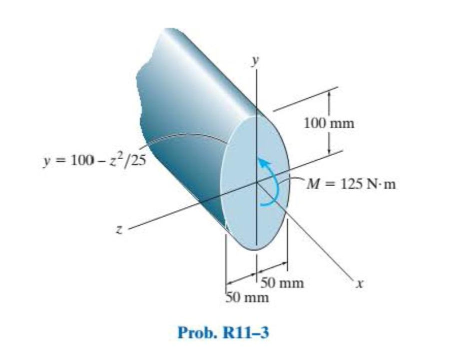
Chapter 11, Problem 3RP
A shaft is made of a polymer having a parabolic upper and lower cross section. If it resists a moment of M = 125 N·m, determine the maximum bending stress in the material (a) using the flexure formula and (b) using integration. Sketch a three-dimensional view of the stress distribution acting over the cross-sectional area. Hint: The moment of inertia is determined using Eq. A–3 of Appendix A.
Expert Solution & Answer
Want to see the full answer?
Check out a sample textbook solution
Students have asked these similar questions
The internal loadings at a cross section through the
120-mm-diameter drive shaft of a turbine consist of an
axial force of 12.5 kN, a bending moment of 1.2 kN - m,
and a torsional moment of 2.25 kN m. (Eigure 1).
Figure
1.2 kN-m
12.5 kN
1 of 1
2.25 kN-m
The 46-mm diameter shaft is supported by a smooth thrust bearing at A and a smooth
journal bearing at B. The pulleys C and D are subjected to the vertical and horizontal
loadings shown in the figure below. (Figure 1)
Part A
Determine the absolute maximum bending stress in the shaft.
Express your answer to three significant figures and include the appropriate units.
?
Omax = 10.7
MPa
Submit
Previous Answers Request Answer
X Incorrect; Try Again; 29 attempts remaining
Provide Feedback
Figure
150 N
400 mm
150 N
300 N 300 N
400 mm
400 mm
A leaf spring 75 cm long is required to carry a
central load of 8 kN. If the central deflection is not to exceed 2 cm and
bending stress no greater than 200 MPa, determine the thickness, width
and number of plates.
Also compute the radius to which plates should be curved. As-
sume width of plate to be 12 times its thickness and E = 200 GPa.
Chapter 11 Solutions
Statics and Mechanics of Materials (5th Edition)
Ch. 11.2 - In each case, the beam is subjected to the...Ch. 11.2 - In each ease, express the shear and moment...Ch. 11.2 - In each ease, express the shear and moment...Ch. 11.2 - In each ease, express the shear and moment...Ch. 11.2 - In each ease, express the shear and moment...Ch. 11.2 - Prob. 5FPCh. 11.2 - Prob. 6FPCh. 11.2 - In each ease, draw the shear and moment diagrams...Ch. 11.2 - Prob. 8FPCh. 11.2 - Prob. 1P
Ch. 11.2 - Draw the shear and moment diagrams for the beam,...Ch. 11.2 - Draw the shear and moment diagrams for the beam,...Ch. 11.2 - Express the shear and moment in terms of x for 0 ...Ch. 11.2 - Express the internal shear and moment in the...Ch. 11.2 - Prob. 6PCh. 11.2 - Express the internal shear and moment in terms of...Ch. 11.2 - Draw the shear and moment diagrams for the beam,...Ch. 11.2 - If the force applied to the handle of the load...Ch. 11.2 - Draw the shear and moment diagrams for the shaft....Ch. 11.2 - The crane is used to support the engine, which has...Ch. 11.2 - Prob. 12PCh. 11.2 - Draw the shear and moment diagrams for the beam....Ch. 11.2 - Draw the shear and moment diagrams for the beam....Ch. 11.2 - Members ABC and BD of the counter chair are...Ch. 11.2 - A reinforced concrete pier is used to support the...Ch. 11.2 - Draw the shear and moment diagrams for the beam...Ch. 11.2 - The industrial robot is held in the stationary...Ch. 11.2 - Determine the placement distance a of the roller...Ch. 11.2 - Prob. 20PCh. 11.2 - Draw the shear and moment diagrams for the beam....Ch. 11.2 - Draw the shear and moment diagrams for the...Ch. 11.2 - The 150-lb man sits in the center of the boat,...Ch. 11.2 - Prob. 24PCh. 11.2 - The footing supports the load transmitted by the...Ch. 11.2 - Prob. 26PCh. 11.2 - Prob. 27PCh. 11.2 - Draw the shear and moment diagrams for the beam....Ch. 11.2 - Draw the shear and moment diagrams for the beam....Ch. 11.2 - Prob. 30PCh. 11.2 - Prob. 31PCh. 11.2 - Prob. 32PCh. 11.2 - The shaft is supported by a smooth thrust bearing...Ch. 11.2 - Draw the shear and moment diagrams for the...Ch. 11.2 - Draw the shear and moment diagrams for the beam....Ch. 11.2 - Draw the shear and moment diagrams for the rod....Ch. 11.2 - Draw the shear and moment diagrams for the beam....Ch. 11.2 - Prob. 38PCh. 11.2 - Draw the shear and moment diagrams for the double...Ch. 11.2 - Draw the shear and moment diagrams for the simply...Ch. 11.2 - The compound beam is fixed at A, pin connected at...Ch. 11.2 - Draw the shear and moment diagrams for the...Ch. 11.2 - The compound beam is fixed at A, pin connected at...Ch. 11.2 - Draw the shear and moment diagrams for the beam....Ch. 11.2 - A short link at B is used to connect beams AB and...Ch. 11.2 - The truck is to be used to transport the concrete...Ch. 11.4 - Determine the moment of inertia of the cross...Ch. 11.4 - Prob. 3PPCh. 11.4 - In each case, show how the bending stress acts on...Ch. 11.4 - Prob. 5PPCh. 11.4 - If the beam is subjected to a bending moment of M...Ch. 11.4 - If the beam is subjected to a bending moment of M...Ch. 11.4 - If the beam is subjected to a bending moment of M...Ch. 11.4 - Prob. 12FPCh. 11.4 - If the beam is subjected to a bending moment of M...Ch. 11.4 - An A-36 steel strip has an allowable bending...Ch. 11.4 - Determine the moment M that will produce a maximum...Ch. 11.4 - Determine the maximum tensile and compressive...Ch. 11.4 - The beam is constructed from four pieces of wood,...Ch. 11.4 - The beam is constructed from four pieces of wood,...Ch. 11.4 - The beam is made from three boards nailed together...Ch. 11.4 - Prob. 53PCh. 11.4 - If the built-up beam is subjected to an internal...Ch. 11.4 - If the built-up beam is subjected to an internal...Ch. 11.4 - Prob. 56PCh. 11.4 - Determine the moment M that should be applied to...Ch. 11.4 - Prob. 58PCh. 11.4 - Prob. 59PCh. 11.4 - The beam is subjected to a moment of 15 kip ft....Ch. 11.4 - The beam is subjected to a moment of 15 kip ft....Ch. 11.4 - Prob. 62PCh. 11.4 - The steel shaft has a diameter of 2 in. It is...Ch. 11.4 - The beam is made of steel that has an allowable...Ch. 11.4 - Prob. 65PCh. 11.4 - Solve Prob. 11-65 if the moment M = 50 N m is...Ch. 11.4 - The shaft is supported by smooth journal bearings...Ch. 11.4 - Prob. 68PCh. 11.4 - Prob. 69PCh. 11.4 - The strut on the utility pole supports the cable...Ch. 11.4 - Prob. 71PCh. 11.4 - Prob. 72PCh. 11.4 - Determine the smallest allowable diameter of the...Ch. 11.4 - Prob. 74PCh. 11.4 - The shaft is supported by a thrust bearing at A...Ch. 11.4 - If the intensity of the load w = 15 kN/m,...Ch. 11.4 - If the allowable bending stress is allow = 150...Ch. 11.4 - The beam is subjected to the triangular...Ch. 11.4 - The beam has a rectangular cross section with b =...Ch. 11.4 - Determine the absolute maximum bending stress in...Ch. 11.4 - If the compound beam in Prob. 11-42 has a square...Ch. 11.4 - Prob. 82PCh. 11.4 - Prob. 83PCh. 11.4 - Determine, to the nearest millimeter, the smallest...Ch. 11.4 - Prob. 85PCh. 11.4 - Determine the absolute maximum bending stress in...Ch. 11.4 - Determine the smallest diameter of the shaft to...Ch. 11.4 - Prob. 88PCh. 11.4 - A log that is 2 ft in diameter is to be cut into a...Ch. 11.4 - The simply supported truss is subjected to the...Ch. 11.4 - Prob. 92PCh. 11.4 - Prob. 93PCh. 11.4 - Prob. 94PCh. 11.4 - The beam has the rectangular cross section shown....Ch. 11.5 - Determine the bending stress developed at corners...Ch. 11.5 - Prob. 15FPCh. 11.5 - Prob. 96PCh. 11.5 - Prob. 97PCh. 11.5 - Prob. 98PCh. 11.5 - Prob. 99PCh. 11.5 - Determine the bending stress at point A of the...Ch. 11.5 - The steel shaft is subjected to the two loads. If...Ch. 11.5 - Prob. 102PCh. 11.5 - Prob. 103PCh. 11.5 - Prob. 104PCh. 11 - Determine the shape factor for the wide-flange...Ch. 11 - The compound beam consists of two segments that...Ch. 11 - A shaft is made of a polymer having a parabolic...Ch. 11 - Determine the maximum bending stress in the handle...Ch. 11 - Determine the shear and moment in the beam as...Ch. 11 - A wooden beam has a square cross section as shown....Ch. 11 - Prob. 7RPCh. 11 - The strut has a square cross section a by a and is...
Knowledge Booster


Learn more about
Need a deep-dive on the concept behind this application? Look no further. Learn more about this topic, mechanical-engineering and related others by exploring similar questions and additional content below.Similar questions
- The aluminium machine part shown below is subjected to a moment of M = 75 N.m. Determine the bending stress created at points B and A on the cross section. Sketch the results on a volume element located at each of these points. A- 50mm 50mm 100mm 100mm 20mm B- M=8kN-m 20mmarrow_forwardBelow Figure shows the section of an angle purlin. A bending moment of 5 kN.m is applied to the purlin in a plane at an angle of 30 deg to the vertical y axis. If the sense of the bending moment is such that both its components Mx and My produce tension in the positive xy quadrant, calculate the maximum direct stress in the purlin, stating clearly the point at which it acts. * 100 mm E 10mm 30 C D -10mm 57 MPa. 89 MPa. Non Above O 72 MPa. 125mmarrow_forwardThe bending moment M is applied to the box beam in the x-y plane at the orientation show below. (a) Determine the maximum magnitude of the bending moment M so that the tensile bending stress in the member does not exceed 15 ksi. (b) Determine the angle that the neutral axis makes with the y-axis. (c) The position or positions on the beam where the maximum compressive bending stress occurs given your answer in a. Clearly indicate this on the figure below (also calculate the values) 4 in. B 4 in. M 6 in. 6 in.arrow_forward
- Find the shear force and bending moment at points B and D. Note: B lies just to the right of the 150 lbf force and D is just to the right of the bearing at C. The bearing at A is a thrust bearing, while the bearing at C is a journal bearing. 150 lb A Answer: VB = -100 lbf MB = 750 lbf in VD = 75lbf Mp = -750 lbf in I 15 in. B 15 in. C. D 75 lb 10 in.arrow_forwardA 18-mm-diameter solid steel shaft supports loads PA = 1,400 N and Pc = 2,100 N as shown. Assume L₁ = 100 mm, L₂ = 200 mm, and L3 = 150 mm. The bearing at B can be idealized as a roller support and the bearing at D can be idealized as a pin support. The moment of inertia of the shaft is 5153 mm4. Determine the magnitude of the maximum bending stress in the shaft. B O 150.2 MPa O 317.3 MPa O 205.6 MPa O 244.5 MPa O 266.8 MPa L₂ Pc L3arrow_forwardThe shaft in the diagram below is subjected to bending forces of 8kN at B and 5 kN at C as shown in the diagram. The shaft is supported in bearings near its ends at A and D. Calculate the maximum bending moment in the shaft. Give your answer to 2 d.p. in Nm but do not include units in your answer. e.g. 5000.00 NOT 5000N marrow_forward
- Determine the maximum positive normal bending stress that occurs in member ABC of the engine crane given the following information: Engine weight = 1500 lb Member ABC height (vertical cross sectional dimension) = 7 in Member ABC width (horizontal cross sectional dimension) = 1 in Express your answer to the nearest whole psi value. In your work, draw the shear and moment diagram for member ABC. For the question above, determine the maximum shear stress in member ABC that occurs between points A and B. Express your answer using the nearest whole psi value.arrow_forwardPart B - Moments of inertia of the cross section with respect to the y- and z-axesTo calculate the absolute maximum bending stress in the member using the flexure formula for unsymmetrical bending, the moments of inertia of the cross section must be calculated. Select the correct formulas for these values. Iy=? Part C - Neutral-axis angle due to externally applied momentsThe neutral-axis angle of the cross section being analyzed is the axis along which there is a zero stress value. Determine the neutral-axis angle, α, due to the externally applied moments as measured counterclockwise from the positive z axis in the yz plane.Express your answer to three significant figures and include the appropriate units. α=? Part D - Absolute maximum stress in cross section ABCDDetermine the absolute maximum stress, |σmax|, in cross section ABCD due to the two externally applied moments. |σmax|=?arrow_forwardFind the second moment of area, the location of the neutral axis, and the distances from the neutral axis to the top and bottom surfaces. Consider that the section is transmitting a positive bending moment about the z axis, Mz, where M₂ = 10 kip-in if the dimensions of the section are given in ips units, or M₂ = 1.13 kN·m if the dimensions are in Sl units. Determine the resulting stresses at the top and bottom surfaces and at every abrupt change in the cross section. From the figure, с - 12.5 B A y I 50 100 75 12.5- 12.5 25 D 100 The area is determined to be 3750 mm² The distances from the neutral axis to the top and bottom surfaces are determined to be 57.292 The second moment of area is determined to be 4.293 x 106 mm4. mm and 42.708 ✪ mm.arrow_forward
- Find the second moment of area, the location of the neutral axis, and the distances from the neutral axis to the top and bottom surfaces. Consider that the section is transmitting a positive bending moment about the z axis, Mz, where M₂ = 10 kip-in if the dimensions of the section are given in ips units, or M₂ = 1.13 kN·m if the dimensions are in Sl units. Determine the resulting stresses at the top and bottom surfaces and at every abrupt change in the cross section. From the figure Z 1 in 112 in y in → ← ¹ in 12 in D C B A ++ in The area is determined to be 2.0625 in². The distances from the neutral axis to the top and bottom surfaces are determined to be 0.858 x in and The second moment of area is determined to be 0.447 in 4. 1.017 xin.arrow_forwardConsider that the section is transmitting a positive bending moment about the z axis,Mz, where Mz=10 kip*in if the dimensions of the section are given in ips units, or Mz=1.13kN*m if the dimensions are in SI units. Determine the resulting stresses at the top and bottom surfaces and at every abrupt change in the cross section. Find the second moment of area, the location of the neutral axis, and the distances from the neutral axis to the top and bottom surfaces.arrow_forwardConsider an 8-m long simply supported T-beam with overhangs loaded as shown below. 200 mm w kN/m 50 mm 50 kN-m 50 kN-m 200 mm 2 m 4 m 2 m 50 mm 1. Determine the location of the neutral axis measured from the top of the beam and the moment of inertia (in mm4) of the section about its neutral axis. Draw the shear and bending moment diagrams. Annotate all relevant values and distances. Determine the magnitude of the maximum negative 2. moment. Determine the minimum allowable strength of the beam in tension and the minimum allowable strength of the beam in compression. 3. Determine the maximum allowable load, w (in kN/m), that can be applied pn the beam. 4. B.arrow_forward
arrow_back_ios
SEE MORE QUESTIONS
arrow_forward_ios
Recommended textbooks for you
 Elements Of ElectromagneticsMechanical EngineeringISBN:9780190698614Author:Sadiku, Matthew N. O.Publisher:Oxford University Press
 Mechanics of Materials (10th Edition)Mechanical EngineeringISBN:9780134319650Author:Russell C. HibbelerPublisher:PEARSON
 Thermodynamics: An Engineering ApproachMechanical EngineeringISBN:9781259822674Author:Yunus A. Cengel Dr., Michael A. BolesPublisher:McGraw-Hill Education
 Control Systems EngineeringMechanical EngineeringISBN:9781118170519Author:Norman S. NisePublisher:WILEY
 Mechanics of Materials (MindTap Course List)Mechanical EngineeringISBN:9781337093347Author:Barry J. Goodno, James M. GerePublisher:Cengage Learning
 Engineering Mechanics: StaticsMechanical EngineeringISBN:9781118807330Author:James L. Meriam, L. G. Kraige, J. N. BoltonPublisher:WILEY
Elements Of Electromagnetics
Mechanical Engineering
ISBN:9780190698614
Author:Sadiku, Matthew N. O.
Publisher:Oxford University Press
Mechanics of Materials (10th Edition)
Mechanical Engineering
ISBN:9780134319650
Author:Russell C. Hibbeler
Publisher:PEARSON
Thermodynamics: An Engineering Approach
Mechanical Engineering
ISBN:9781259822674
Author:Yunus A. Cengel Dr., Michael A. Boles
Publisher:McGraw-Hill Education
Control Systems Engineering
Mechanical Engineering
ISBN:9781118170519
Author:Norman S. Nise
Publisher:WILEY
Mechanics of Materials (MindTap Course List)
Mechanical Engineering
ISBN:9781337093347
Author:Barry J. Goodno, James M. Gere
Publisher:Cengage Learning
Engineering Mechanics: Statics
Mechanical Engineering
ISBN:9781118807330
Author:James L. Meriam, L. G. Kraige, J. N. Bolton
Publisher:WILEY
Everything About COMBINED LOADING in 10 Minutes! Mechanics of Materials; Author: Less Boring Lectures;https://www.youtube.com/watch?v=N-PlI900hSg;License: Standard youtube license