
Statics and Mechanics of Materials (5th Edition)
5th Edition
ISBN: 9780134382593
Author: Russell C. Hibbeler
Publisher: PEARSON
expand_more
expand_more
format_list_bulleted
Concept explainers
Videos
Textbook Question
Chapter 11.5, Problem 100P
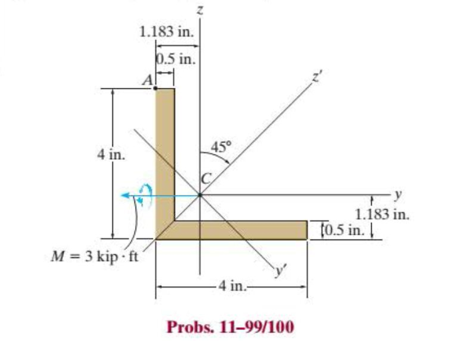
Determine the bending stress at point A of the beam using the result obtained in Prob. 11–98. The moments of inertia of the cross-sectional area about the z and y axes are Iz = Iy = 5.561 in4 and the product of inertia of the cross sectional area with respect to the z and y axes is Iyz = –3.267 in4. (See Appendix A.)
Expert Solution & Answer
Want to see the full answer?
Check out a sample textbook solution
Students have asked these similar questions
Calculate the moment of inertia of the cross section of the beam about its centroidal xo-axis.
Assume h = 156 mm, b = 133 mm, t = 25 mm.
h
Yo
Answer: Ixo =i
(106) mm4
The cross section of a bearing block is shown in the figure by the shaded area. Calculate the moment of inertia of the section about its
base a-a.
Assume b = 13 in., h = 7 in., r= 3 in, R = 4 in.
R
h
a -
--a
b
Answer: Ig-a = i
in.4
The cross section of a bearing block is shown in the figure by the shaded area. Calculate the moment of inertia of the section about its
base a-a.
Assume b = 29 in., h = 7 in., r = 4 in, R = 8 in.
a
Answer: la-ai
r
b
R
in.4
h
Chapter 11 Solutions
Statics and Mechanics of Materials (5th Edition)
Ch. 11.2 - In each case, the beam is subjected to the...Ch. 11.2 - In each ease, express the shear and moment...Ch. 11.2 - In each ease, express the shear and moment...Ch. 11.2 - In each ease, express the shear and moment...Ch. 11.2 - In each ease, express the shear and moment...Ch. 11.2 - Prob. 5FPCh. 11.2 - Prob. 6FPCh. 11.2 - In each ease, draw the shear and moment diagrams...Ch. 11.2 - Prob. 8FPCh. 11.2 - Prob. 1P
Ch. 11.2 - Draw the shear and moment diagrams for the beam,...Ch. 11.2 - Draw the shear and moment diagrams for the beam,...Ch. 11.2 - Express the shear and moment in terms of x for 0 ...Ch. 11.2 - Express the internal shear and moment in the...Ch. 11.2 - Prob. 6PCh. 11.2 - Express the internal shear and moment in terms of...Ch. 11.2 - Draw the shear and moment diagrams for the beam,...Ch. 11.2 - If the force applied to the handle of the load...Ch. 11.2 - Draw the shear and moment diagrams for the shaft....Ch. 11.2 - The crane is used to support the engine, which has...Ch. 11.2 - Prob. 12PCh. 11.2 - Draw the shear and moment diagrams for the beam....Ch. 11.2 - Draw the shear and moment diagrams for the beam....Ch. 11.2 - Members ABC and BD of the counter chair are...Ch. 11.2 - A reinforced concrete pier is used to support the...Ch. 11.2 - Draw the shear and moment diagrams for the beam...Ch. 11.2 - The industrial robot is held in the stationary...Ch. 11.2 - Determine the placement distance a of the roller...Ch. 11.2 - Prob. 20PCh. 11.2 - Draw the shear and moment diagrams for the beam....Ch. 11.2 - Draw the shear and moment diagrams for the...Ch. 11.2 - The 150-lb man sits in the center of the boat,...Ch. 11.2 - Prob. 24PCh. 11.2 - The footing supports the load transmitted by the...Ch. 11.2 - Prob. 26PCh. 11.2 - Prob. 27PCh. 11.2 - Draw the shear and moment diagrams for the beam....Ch. 11.2 - Draw the shear and moment diagrams for the beam....Ch. 11.2 - Prob. 30PCh. 11.2 - Prob. 31PCh. 11.2 - Prob. 32PCh. 11.2 - The shaft is supported by a smooth thrust bearing...Ch. 11.2 - Draw the shear and moment diagrams for the...Ch. 11.2 - Draw the shear and moment diagrams for the beam....Ch. 11.2 - Draw the shear and moment diagrams for the rod....Ch. 11.2 - Draw the shear and moment diagrams for the beam....Ch. 11.2 - Prob. 38PCh. 11.2 - Draw the shear and moment diagrams for the double...Ch. 11.2 - Draw the shear and moment diagrams for the simply...Ch. 11.2 - The compound beam is fixed at A, pin connected at...Ch. 11.2 - Draw the shear and moment diagrams for the...Ch. 11.2 - The compound beam is fixed at A, pin connected at...Ch. 11.2 - Draw the shear and moment diagrams for the beam....Ch. 11.2 - A short link at B is used to connect beams AB and...Ch. 11.2 - The truck is to be used to transport the concrete...Ch. 11.4 - Determine the moment of inertia of the cross...Ch. 11.4 - Prob. 3PPCh. 11.4 - In each case, show how the bending stress acts on...Ch. 11.4 - Prob. 5PPCh. 11.4 - If the beam is subjected to a bending moment of M...Ch. 11.4 - If the beam is subjected to a bending moment of M...Ch. 11.4 - If the beam is subjected to a bending moment of M...Ch. 11.4 - Prob. 12FPCh. 11.4 - If the beam is subjected to a bending moment of M...Ch. 11.4 - An A-36 steel strip has an allowable bending...Ch. 11.4 - Determine the moment M that will produce a maximum...Ch. 11.4 - Determine the maximum tensile and compressive...Ch. 11.4 - The beam is constructed from four pieces of wood,...Ch. 11.4 - The beam is constructed from four pieces of wood,...Ch. 11.4 - The beam is made from three boards nailed together...Ch. 11.4 - Prob. 53PCh. 11.4 - If the built-up beam is subjected to an internal...Ch. 11.4 - If the built-up beam is subjected to an internal...Ch. 11.4 - Prob. 56PCh. 11.4 - Determine the moment M that should be applied to...Ch. 11.4 - Prob. 58PCh. 11.4 - Prob. 59PCh. 11.4 - The beam is subjected to a moment of 15 kip ft....Ch. 11.4 - The beam is subjected to a moment of 15 kip ft....Ch. 11.4 - Prob. 62PCh. 11.4 - The steel shaft has a diameter of 2 in. It is...Ch. 11.4 - The beam is made of steel that has an allowable...Ch. 11.4 - Prob. 65PCh. 11.4 - Solve Prob. 11-65 if the moment M = 50 N m is...Ch. 11.4 - The shaft is supported by smooth journal bearings...Ch. 11.4 - Prob. 68PCh. 11.4 - Prob. 69PCh. 11.4 - The strut on the utility pole supports the cable...Ch. 11.4 - Prob. 71PCh. 11.4 - Prob. 72PCh. 11.4 - Determine the smallest allowable diameter of the...Ch. 11.4 - Prob. 74PCh. 11.4 - The shaft is supported by a thrust bearing at A...Ch. 11.4 - If the intensity of the load w = 15 kN/m,...Ch. 11.4 - If the allowable bending stress is allow = 150...Ch. 11.4 - The beam is subjected to the triangular...Ch. 11.4 - The beam has a rectangular cross section with b =...Ch. 11.4 - Determine the absolute maximum bending stress in...Ch. 11.4 - If the compound beam in Prob. 11-42 has a square...Ch. 11.4 - Prob. 82PCh. 11.4 - Prob. 83PCh. 11.4 - Determine, to the nearest millimeter, the smallest...Ch. 11.4 - Prob. 85PCh. 11.4 - Determine the absolute maximum bending stress in...Ch. 11.4 - Determine the smallest diameter of the shaft to...Ch. 11.4 - Prob. 88PCh. 11.4 - A log that is 2 ft in diameter is to be cut into a...Ch. 11.4 - The simply supported truss is subjected to the...Ch. 11.4 - Prob. 92PCh. 11.4 - Prob. 93PCh. 11.4 - Prob. 94PCh. 11.4 - The beam has the rectangular cross section shown....Ch. 11.5 - Determine the bending stress developed at corners...Ch. 11.5 - Prob. 15FPCh. 11.5 - Prob. 96PCh. 11.5 - Prob. 97PCh. 11.5 - Prob. 98PCh. 11.5 - Prob. 99PCh. 11.5 - Determine the bending stress at point A of the...Ch. 11.5 - The steel shaft is subjected to the two loads. If...Ch. 11.5 - Prob. 102PCh. 11.5 - Prob. 103PCh. 11.5 - Prob. 104PCh. 11 - Determine the shape factor for the wide-flange...Ch. 11 - The compound beam consists of two segments that...Ch. 11 - A shaft is made of a polymer having a parabolic...Ch. 11 - Determine the maximum bending stress in the handle...Ch. 11 - Determine the shear and moment in the beam as...Ch. 11 - A wooden beam has a square cross section as shown....Ch. 11 - Prob. 7RPCh. 11 - The strut has a square cross section a by a and is...
Knowledge Booster


Learn more about
Need a deep-dive on the concept behind this application? Look no further. Learn more about this topic, mechanical-engineering and related others by exploring similar questions and additional content below.Similar questions
- The cross section of a bearing block is shown in the figure by the shaded area. Calculate the moment of inertia of the section about its base a-a. Assume b = 16 in., h = 6 in., r = 3 in, R = 5 in. h b Answer: I-a = i in. 4arrow_forwardA symmetrical Inverted T section has the following specifications : Width of the web (W) = 100 mm,Height of the section (H) = 150 mm, Thickness of web and leg (T) = 30 mm. Determine the moment of inertia of the section with respect to the base. T= 30 mm ТОР LEG H=150mm WEB T=30 mm BASE -W = 100 mmarrow_forwardPart A - Free-body diagram of the resolved components of the moments The two externally applied moments can be resolved into their respective y and z components. Determine the moments in each principal direction, My and Mz, and draw the corresponding free-body diagram. Part B - Moments of inertia of the cross section with respect to the y- and z-axes To calculate the absolute maximum bending stress in the member using the flexure formula for unsymmetrical bending, the moments of inertia of the cross section must be calculated. Select the correct formulas for these values. Iy=? Part C - Neutral-axis angle due to externally applied moments The neutral-axis angle of the cross section being analyzed is the axis along which there is a zero stress value. Determine the neutral-axis angle, αα, due to the externally applied moments as measured counterclockwise from the positive z axis in the yz plane. |α| =? Part D - Absolute maximum stress in cross section ABCD…arrow_forward
- Determine the bending stress at point A of the beam, and the orientation of the neutral axis. Using the method in Appendix A, the principal moments of inertia of the crosssection are Iz = 8.828 in4 and Iy = 2.295 in4, where z and y' are the principal axes. Solve the problem using Eq.arrow_forward1. For a simple supported beam with a bending moment diagram shown, determine the following a. Area moment of inertia of the given cross section b. Maximum tensile flexural stress and its location c. Maximum compressive flexural stresses and its location The beam has the triangular section shown: The beam has the triangular section shown. 200 mm 676 E M (Nm) 300 mm - 1200 - 1560 X-sectionarrow_forwardThe dimensions of the double-box beam cross section shown in Figure are (b= 150 mm), (d= 50 mm), and (t= 4 mm). Determine the Moment of inertia about z * :axis (Iz) y d (Гур.) 610390 mm4 O 610400 mm4 710488 mm4 610500 mm4arrow_forward
- A built-up beam is constructed by welding two channels separated by a distance b = 1.25 in to two (5 in × 0.5 in) plates. y X ky Channel properties: C3x6 Area = 1.76 in² D = 3 in bf = 1.6 in x = 0.455 in Ī II Ī yy = 2.07 in* = = 0.3 in* Determine the moment of inertia and radii of gyration of the composite beam with respect to the x- and y-axes. Iz kz Iyarrow_forwardUsing the techniques outlined in Appendix A, Example A.5 or A.6, the Z section has principal moments of inertia of I, = 0.060(10-3) mª and I; = 0.471(10-3) m*, computed about the prin- cipal axes of inertial y and z, respectively. If the section is subjected to an internal moment of M = 250 N-m directed horizontally as shown, determine the stress at point B, and the orienta- tion of the neutral axis. 50 mm 200 mm 32.9° 250 N-m 200 mm 50 mm B 50 mm -300 mmarrow_forwardA beam having a tee-shaped cross section is subjected to equal 18 kN-m bending moments, as shown. Assume bf = 125 mm, tf = 25 mm, d = 185 mm, tw = 20 mm. The cross-sectional dimensions of the beam are also shown. a.Determine the centroid location (measured upward from the bottom), in mm rounded to the nearest tenths. b.Determine the moment of inertia about the z axis. Express your answer in (106) mm4 rounded to three significant figures. c. Determine the controlling section modulus about the z axis. Express your answer in (103) mm3 rounded to three significant figures. d. Determine the controlling section modulus about the z axis. Express your answer in (103) mm3 rounded to three significant figures.arrow_forward
arrow_back_ios
arrow_forward_ios
Recommended textbooks for you
 Elements Of ElectromagneticsMechanical EngineeringISBN:9780190698614Author:Sadiku, Matthew N. O.Publisher:Oxford University Press
 Mechanics of Materials (10th Edition)Mechanical EngineeringISBN:9780134319650Author:Russell C. HibbelerPublisher:PEARSON
 Thermodynamics: An Engineering ApproachMechanical EngineeringISBN:9781259822674Author:Yunus A. Cengel Dr., Michael A. BolesPublisher:McGraw-Hill Education
 Control Systems EngineeringMechanical EngineeringISBN:9781118170519Author:Norman S. NisePublisher:WILEY
 Mechanics of Materials (MindTap Course List)Mechanical EngineeringISBN:9781337093347Author:Barry J. Goodno, James M. GerePublisher:Cengage Learning
 Engineering Mechanics: StaticsMechanical EngineeringISBN:9781118807330Author:James L. Meriam, L. G. Kraige, J. N. BoltonPublisher:WILEY
Elements Of Electromagnetics
Mechanical Engineering
ISBN:9780190698614
Author:Sadiku, Matthew N. O.
Publisher:Oxford University Press
Mechanics of Materials (10th Edition)
Mechanical Engineering
ISBN:9780134319650
Author:Russell C. Hibbeler
Publisher:PEARSON
Thermodynamics: An Engineering Approach
Mechanical Engineering
ISBN:9781259822674
Author:Yunus A. Cengel Dr., Michael A. Boles
Publisher:McGraw-Hill Education
Control Systems Engineering
Mechanical Engineering
ISBN:9781118170519
Author:Norman S. Nise
Publisher:WILEY
Mechanics of Materials (MindTap Course List)
Mechanical Engineering
ISBN:9781337093347
Author:Barry J. Goodno, James M. Gere
Publisher:Cengage Learning
Engineering Mechanics: Statics
Mechanical Engineering
ISBN:9781118807330
Author:James L. Meriam, L. G. Kraige, J. N. Bolton
Publisher:WILEY
moment of inertia; Author: NCERT OFFICIAL;https://www.youtube.com/watch?v=A4KhJYrt4-s;License: Standard YouTube License, CC-BY