
Statics and Mechanics of Materials (5th Edition)
5th Edition
ISBN: 9780134382593
Author: Russell C. Hibbeler
Publisher: PEARSON
expand_more
expand_more
format_list_bulleted
Concept explainers
Videos
Textbook Question
Chapter 11.2, Problem 4P
Express the shear and moment in terms of x for 0 < x < 3 m and 3 m < x < 4.5 m, and then draw the shear and moment diagrams for the simply supported beam.
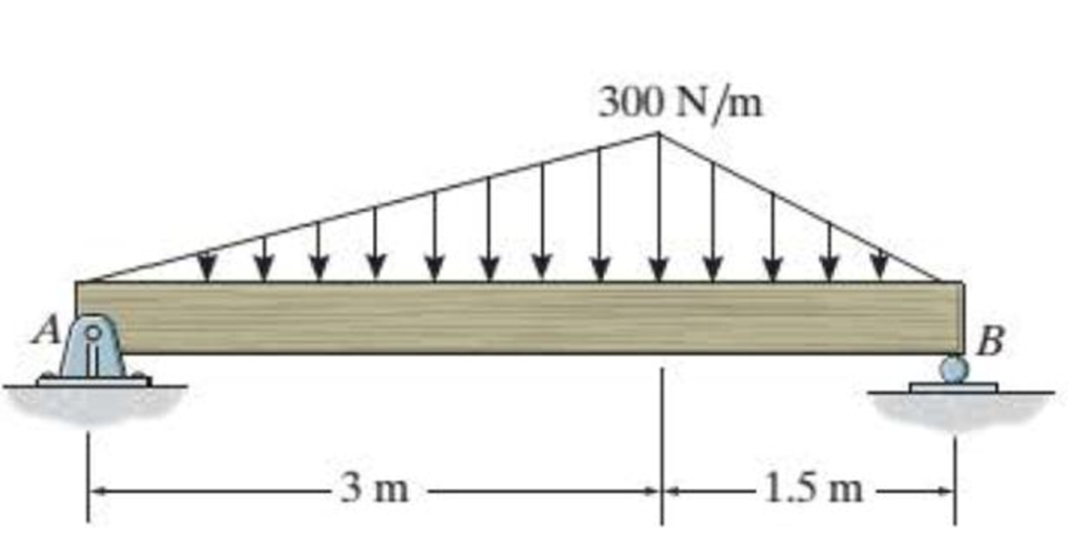
Prob. 11-4
Expert Solution & Answer
Want to see the full answer?
Check out a sample textbook solution
Students have asked these similar questions
36
2) Use the method of MEMBERS to determine the true magnitude and
direction of the forces in members1 and 2 of the frame shown below
in Fig 3.2.
300lbs/ft
member-1
member-2
30°
Fig 3.2.
https://brightspace.cuny.edu/d21/le/content/433117/viewContent/29873977/View
Can you solve this for me?
5670 mm
The apartment in the ground floor of three floors building in Fig. in Baghdad city. The details of
walls, roof, windows and door are shown. The window is a double glazing and air space thickness
is 1.3cm Poorly Fitted-with Storm Sash with wood strip and storm window of 0.6 cm glass
thickness. The thickness of door is 2.5 cm. The door is Poor Installation. There are two peoples
in each room. The height of room is 280 cm. assume the indoor design conditions are 25°C DBT
and 50 RH, and moisture content of 8 gw/kga. The moisture content of outdoor is 10.5 gw/kga.
Calculate heat gain for living room :
الشقة في الطابق الأرضي من مبنى ثلاثة طوابق في مدينة بغداد يظهر في مخطط الشقة تفاصيل الجدران والسقف
والنوافذ والباب. النافذة عبارة عن زجاج مزدوج وسمك الفراغ الهوائي 1.3 سم ضعيف الاحكام مع ساتر حماية مع إطار
خشبي والنافذة بسماكة زجاج 0.6 سم سماكة الباب 2.5 سم. الباب هو تركيب ضعيف هناك شخصان في كل غرفة.
ارتفاع الغرفة 280 سم. افترض أن ظروف التصميم الداخلي هي DBT25 و R50 ، ومحتوى الرطوبة 8…
Chapter 11 Solutions
Statics and Mechanics of Materials (5th Edition)
Ch. 11.2 - In each case, the beam is subjected to the...Ch. 11.2 - In each ease, express the shear and moment...Ch. 11.2 - In each ease, express the shear and moment...Ch. 11.2 - In each ease, express the shear and moment...Ch. 11.2 - In each ease, express the shear and moment...Ch. 11.2 - Prob. 5FPCh. 11.2 - Prob. 6FPCh. 11.2 - In each ease, draw the shear and moment diagrams...Ch. 11.2 - Prob. 8FPCh. 11.2 - Prob. 1P
Ch. 11.2 - Draw the shear and moment diagrams for the beam,...Ch. 11.2 - Draw the shear and moment diagrams for the beam,...Ch. 11.2 - Express the shear and moment in terms of x for 0 ...Ch. 11.2 - Express the internal shear and moment in the...Ch. 11.2 - Prob. 6PCh. 11.2 - Express the internal shear and moment in terms of...Ch. 11.2 - Draw the shear and moment diagrams for the beam,...Ch. 11.2 - If the force applied to the handle of the load...Ch. 11.2 - Draw the shear and moment diagrams for the shaft....Ch. 11.2 - The crane is used to support the engine, which has...Ch. 11.2 - Prob. 12PCh. 11.2 - Draw the shear and moment diagrams for the beam....Ch. 11.2 - Draw the shear and moment diagrams for the beam....Ch. 11.2 - Members ABC and BD of the counter chair are...Ch. 11.2 - A reinforced concrete pier is used to support the...Ch. 11.2 - Draw the shear and moment diagrams for the beam...Ch. 11.2 - The industrial robot is held in the stationary...Ch. 11.2 - Determine the placement distance a of the roller...Ch. 11.2 - Prob. 20PCh. 11.2 - Draw the shear and moment diagrams for the beam....Ch. 11.2 - Draw the shear and moment diagrams for the...Ch. 11.2 - The 150-lb man sits in the center of the boat,...Ch. 11.2 - Prob. 24PCh. 11.2 - The footing supports the load transmitted by the...Ch. 11.2 - Prob. 26PCh. 11.2 - Prob. 27PCh. 11.2 - Draw the shear and moment diagrams for the beam....Ch. 11.2 - Draw the shear and moment diagrams for the beam....Ch. 11.2 - Prob. 30PCh. 11.2 - Prob. 31PCh. 11.2 - Prob. 32PCh. 11.2 - The shaft is supported by a smooth thrust bearing...Ch. 11.2 - Draw the shear and moment diagrams for the...Ch. 11.2 - Draw the shear and moment diagrams for the beam....Ch. 11.2 - Draw the shear and moment diagrams for the rod....Ch. 11.2 - Draw the shear and moment diagrams for the beam....Ch. 11.2 - Prob. 38PCh. 11.2 - Draw the shear and moment diagrams for the double...Ch. 11.2 - Draw the shear and moment diagrams for the simply...Ch. 11.2 - The compound beam is fixed at A, pin connected at...Ch. 11.2 - Draw the shear and moment diagrams for the...Ch. 11.2 - The compound beam is fixed at A, pin connected at...Ch. 11.2 - Draw the shear and moment diagrams for the beam....Ch. 11.2 - A short link at B is used to connect beams AB and...Ch. 11.2 - The truck is to be used to transport the concrete...Ch. 11.4 - Determine the moment of inertia of the cross...Ch. 11.4 - Prob. 3PPCh. 11.4 - In each case, show how the bending stress acts on...Ch. 11.4 - Prob. 5PPCh. 11.4 - If the beam is subjected to a bending moment of M...Ch. 11.4 - If the beam is subjected to a bending moment of M...Ch. 11.4 - If the beam is subjected to a bending moment of M...Ch. 11.4 - Prob. 12FPCh. 11.4 - If the beam is subjected to a bending moment of M...Ch. 11.4 - An A-36 steel strip has an allowable bending...Ch. 11.4 - Determine the moment M that will produce a maximum...Ch. 11.4 - Determine the maximum tensile and compressive...Ch. 11.4 - The beam is constructed from four pieces of wood,...Ch. 11.4 - The beam is constructed from four pieces of wood,...Ch. 11.4 - The beam is made from three boards nailed together...Ch. 11.4 - Prob. 53PCh. 11.4 - If the built-up beam is subjected to an internal...Ch. 11.4 - If the built-up beam is subjected to an internal...Ch. 11.4 - Prob. 56PCh. 11.4 - Determine the moment M that should be applied to...Ch. 11.4 - Prob. 58PCh. 11.4 - Prob. 59PCh. 11.4 - The beam is subjected to a moment of 15 kip ft....Ch. 11.4 - The beam is subjected to a moment of 15 kip ft....Ch. 11.4 - Prob. 62PCh. 11.4 - The steel shaft has a diameter of 2 in. It is...Ch. 11.4 - The beam is made of steel that has an allowable...Ch. 11.4 - Prob. 65PCh. 11.4 - Solve Prob. 11-65 if the moment M = 50 N m is...Ch. 11.4 - The shaft is supported by smooth journal bearings...Ch. 11.4 - Prob. 68PCh. 11.4 - Prob. 69PCh. 11.4 - The strut on the utility pole supports the cable...Ch. 11.4 - Prob. 71PCh. 11.4 - Prob. 72PCh. 11.4 - Determine the smallest allowable diameter of the...Ch. 11.4 - Prob. 74PCh. 11.4 - The shaft is supported by a thrust bearing at A...Ch. 11.4 - If the intensity of the load w = 15 kN/m,...Ch. 11.4 - If the allowable bending stress is allow = 150...Ch. 11.4 - The beam is subjected to the triangular...Ch. 11.4 - The beam has a rectangular cross section with b =...Ch. 11.4 - Determine the absolute maximum bending stress in...Ch. 11.4 - If the compound beam in Prob. 11-42 has a square...Ch. 11.4 - Prob. 82PCh. 11.4 - Prob. 83PCh. 11.4 - Determine, to the nearest millimeter, the smallest...Ch. 11.4 - Prob. 85PCh. 11.4 - Determine the absolute maximum bending stress in...Ch. 11.4 - Determine the smallest diameter of the shaft to...Ch. 11.4 - Prob. 88PCh. 11.4 - A log that is 2 ft in diameter is to be cut into a...Ch. 11.4 - The simply supported truss is subjected to the...Ch. 11.4 - Prob. 92PCh. 11.4 - Prob. 93PCh. 11.4 - Prob. 94PCh. 11.4 - The beam has the rectangular cross section shown....Ch. 11.5 - Determine the bending stress developed at corners...Ch. 11.5 - Prob. 15FPCh. 11.5 - Prob. 96PCh. 11.5 - Prob. 97PCh. 11.5 - Prob. 98PCh. 11.5 - Prob. 99PCh. 11.5 - Determine the bending stress at point A of the...Ch. 11.5 - The steel shaft is subjected to the two loads. If...Ch. 11.5 - Prob. 102PCh. 11.5 - Prob. 103PCh. 11.5 - Prob. 104PCh. 11 - Determine the shape factor for the wide-flange...Ch. 11 - The compound beam consists of two segments that...Ch. 11 - A shaft is made of a polymer having a parabolic...Ch. 11 - Determine the maximum bending stress in the handle...Ch. 11 - Determine the shear and moment in the beam as...Ch. 11 - A wooden beam has a square cross section as shown....Ch. 11 - Prob. 7RPCh. 11 - The strut has a square cross section a by a and is...
Additional Engineering Textbook Solutions
Find more solutions based on key concepts
What types of coolant are used in vehicles?
Automotive Technology: Principles, Diagnosis, And Service (6th Edition) (halderman Automotive Series)
CONCEPT QUESTIONS
15.CQ3 The ball rolls without slipping on the fixed surface as shown. What is the direction ...
Vector Mechanics for Engineers: Statics and Dynamics
The solid steel shaft AC has a diameter of 25 mm and is supported by smooth bearings at D and E. It is coupled ...
Mechanics of Materials (10th Edition)
Computers process data under the control of sets of instructions called
Java How to Program, Early Objects (11th Edition) (Deitel: How to Program)
How is the hydrodynamic entry length defined for flow in a pipe? Is the entry length longer in laminar or turbu...
Fluid Mechanics: Fundamentals and Applications
Why is the study of database technology important?
Database Concepts (8th Edition)
Knowledge Booster


Learn more about
Need a deep-dive on the concept behind this application? Look no further. Learn more about this topic, mechanical-engineering and related others by exploring similar questions and additional content below.Similar questions
- How do i solve this problem?arrow_forwardQ4/ A compressor is driven motor by mean of a flat belt of thickness 10 mm and a width of 250 mm. The motor pulley is 300 mm diameter and run at 900 rpm and the compressor pulley is 1500 mm diameter. The shaft center distance is 1.5 m. The angle of contact of the smaller pulley is 220° and on the larger pulley is 270°. The coefficient of friction between the belt and the small pulley is 0.3, and between the belt and the large pulley is 0.25. The maximum allowable belt stress is 2 MPa and the belt density is 970 kg/m³. (a) What is the power capacity of the drive and (b) If the small pulley replaced by V-grooved pulley of diameter 300 mm, grooved angle of 34° and the coefficient of friction between belt and grooved pulley is 0.35. What will be the power capacity in this case, assuming that the diameter of the large pulley remain the same of 1500 mm.arrow_forwardYou are tasked with designing a power drive system to transmit power between a motor and a conveyor belt in a manufacturing facility as illustrated in figure. The design must ensure efficient power transmission, reliability, and safety. Given the following specifications and constraints, design drive system for this application: Specifications: Motor Power: The electric motor provides 10 kW of power at 1,500 RPM. Output Speed: The output shaft should rotate at 150 rpm. Design Decisions: Transmission ratio: Determine the necessary drive ratio for the system. Shaft Diameter: Design the shafts for both the motor and the conveyor end. Material Selection: Choose appropriate materials for the gears, shafts. Bearings: Select suitable rolling element bearings. Constraints: Space Limitation: The available space for the gear drive system is limited to a 1-meter-long section. Attribute 4 of CEP Depth of knowledge required Fundamentals-based, first principles analytical approach…arrow_forward
- - | العنوان In non-continuous dieless drawing process for copper tube as shown in Fig. (1), take the following data: Do-20mm, to=3mm, D=12mm, ti/to=0.6 and v.-15mm/s. Calculate: (1) area reduction RA, (2) drawing velocity v. Knowing that: ti: final thickness V. Fig. (1) ofthrearrow_forwardA direct extrusion operation produces the cross section shown in Fig. (2) from an aluminum billet whose diameter 160 mm and length - 700 mm. Determine the length of the extruded section at the end of the operation if the die angle -14° 60 X Fig. (2) Note: all dimensions in mm.arrow_forwardFor hot rolling processes, show that the average strain rate can be given as: = (1+5)√RdIn(+1)arrow_forward
- : +0 usão العنوان on to A vertical true centrifugal casting process is used to produce bushings that are 250 mm long and 200 mm in outside diameter. If the rotational speed during solidification is 500 rev/min, determine the inside radii at the top and bottom of the bushing if R-2R. Take: -9.81 mis ۲/۱ ostrararrow_forward: +0 العنوان use only In conventional drawing of a stainless steel wire, the original diameter D.-3mm, the area reduction at each die stand r-40%, and the proposed final diameter D.-0.5mm, how many die stands are required to complete this process. онarrow_forwardIn non-continuous dieless drawing process for copper tube as shown in Fig. (1), take the following data: Do-20mm, to=3mm, D=12mm, ti/to=0.6 and vo-15mm/s. Calculate: (1) area reduction RA, (2) drawing velocity v. Knowing that: t₁: final thickness D₁ V. Fig. (1) Darrow_forward
- A vertical true centrifugal casting process is used to produce bushings that are 250 mm long and 200 mm in outside diameter. If the rotational speed during solidification is 500 rev/min, determine the inside radii at the top and bottom of the bushing if R-2Rb. Take: 8-9.81 m/sarrow_forwardIn conventional drawing of a stainless steel wire, the original diameter D.-3mm, the area reduction at each die stand r-40%, and the proposed final diameter D₁-0.5mm, how many die stands are required to complete this process.arrow_forwardA vertical true centrifugal casting process is used to produce bushings that are 250 mm long and 200 mm in outside diameter. If the rotational speed during solidification is 500 rev/min, determine the inside radii at the top and bottom of the bushing if R-2Rb. Take: 8-9.81 m/sarrow_forward
arrow_back_ios
SEE MORE QUESTIONS
arrow_forward_ios
Recommended textbooks for you
 Elements Of ElectromagneticsMechanical EngineeringISBN:9780190698614Author:Sadiku, Matthew N. O.Publisher:Oxford University Press
 Mechanics of Materials (10th Edition)Mechanical EngineeringISBN:9780134319650Author:Russell C. HibbelerPublisher:PEARSON
 Thermodynamics: An Engineering ApproachMechanical EngineeringISBN:9781259822674Author:Yunus A. Cengel Dr., Michael A. BolesPublisher:McGraw-Hill Education
 Control Systems EngineeringMechanical EngineeringISBN:9781118170519Author:Norman S. NisePublisher:WILEY
 Mechanics of Materials (MindTap Course List)Mechanical EngineeringISBN:9781337093347Author:Barry J. Goodno, James M. GerePublisher:Cengage Learning
 Engineering Mechanics: StaticsMechanical EngineeringISBN:9781118807330Author:James L. Meriam, L. G. Kraige, J. N. BoltonPublisher:WILEY
Elements Of Electromagnetics
Mechanical Engineering
ISBN:9780190698614
Author:Sadiku, Matthew N. O.
Publisher:Oxford University Press
Mechanics of Materials (10th Edition)
Mechanical Engineering
ISBN:9780134319650
Author:Russell C. Hibbeler
Publisher:PEARSON
Thermodynamics: An Engineering Approach
Mechanical Engineering
ISBN:9781259822674
Author:Yunus A. Cengel Dr., Michael A. Boles
Publisher:McGraw-Hill Education
Control Systems Engineering
Mechanical Engineering
ISBN:9781118170519
Author:Norman S. Nise
Publisher:WILEY
Mechanics of Materials (MindTap Course List)
Mechanical Engineering
ISBN:9781337093347
Author:Barry J. Goodno, James M. Gere
Publisher:Cengage Learning
Engineering Mechanics: Statics
Mechanical Engineering
ISBN:9781118807330
Author:James L. Meriam, L. G. Kraige, J. N. Bolton
Publisher:WILEY
Understanding Shear Force and Bending Moment Diagrams; Author: The Efficient Engineer;https://www.youtube.com/watch?v=C-FEVzI8oe8;License: Standard YouTube License, CC-BY
Bending Stress; Author: moodlemech;https://www.youtube.com/watch?v=9QIqewkE6xM;License: Standard Youtube License