
Statics and Mechanics of Materials (5th Edition)
5th Edition
ISBN: 9780134382593
Author: Russell C. Hibbeler
Publisher: PEARSON
expand_more
expand_more
format_list_bulleted
Videos
Textbook Question
Chapter 11.4, Problem 70P
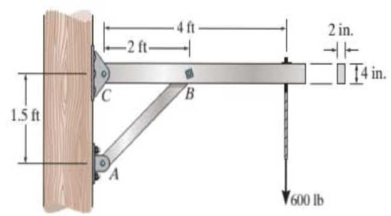
The strut on the utility pole supports the cable having a weight of 600 lb. Determine the absolute maximum bending stress in the strut if A, B, and C are assumed to be pinned.
Prob. 11-70
Expert Solution & Answer
Want to see the full answer?
Check out a sample textbook solution
Students have asked these similar questions
: +0
usão
العنوان
on
to
A vertical true centrifugal casting process is used to produce bushings that are 250 mm
long and 200 mm in outside diameter. If the rotational speed during solidification is 500
rev/min, determine the inside radii at the top and bottom of the bushing if R-2R. Take:
-9.81 mis
۲/۱
ostrar
: +0
العنوان
use only
In conventional drawing of a stainless steel wire, the original diameter D.-3mm, the area
reduction at each die stand r-40%, and the proposed final diameter D.-0.5mm, how many
die stands are required to complete this process.
он
In non-continuous dieless drawing process for copper tube as shown in Fig. (1), take the
following data: Do-20mm, to=3mm, D=12mm, ti/to=0.6 and vo-15mm/s. Calculate: (1)
area reduction RA, (2) drawing velocity v. Knowing that: t₁: final thickness
D₁
V.
Fig. (1)
D
Chapter 11 Solutions
Statics and Mechanics of Materials (5th Edition)
Ch. 11.2 - In each case, the beam is subjected to the...Ch. 11.2 - In each ease, express the shear and moment...Ch. 11.2 - In each ease, express the shear and moment...Ch. 11.2 - In each ease, express the shear and moment...Ch. 11.2 - In each ease, express the shear and moment...Ch. 11.2 - Prob. 5FPCh. 11.2 - Prob. 6FPCh. 11.2 - In each ease, draw the shear and moment diagrams...Ch. 11.2 - Prob. 8FPCh. 11.2 - Prob. 1P
Ch. 11.2 - Draw the shear and moment diagrams for the beam,...Ch. 11.2 - Draw the shear and moment diagrams for the beam,...Ch. 11.2 - Express the shear and moment in terms of x for 0 ...Ch. 11.2 - Express the internal shear and moment in the...Ch. 11.2 - Prob. 6PCh. 11.2 - Express the internal shear and moment in terms of...Ch. 11.2 - Draw the shear and moment diagrams for the beam,...Ch. 11.2 - If the force applied to the handle of the load...Ch. 11.2 - Draw the shear and moment diagrams for the shaft....Ch. 11.2 - The crane is used to support the engine, which has...Ch. 11.2 - Prob. 12PCh. 11.2 - Draw the shear and moment diagrams for the beam....Ch. 11.2 - Draw the shear and moment diagrams for the beam....Ch. 11.2 - Members ABC and BD of the counter chair are...Ch. 11.2 - A reinforced concrete pier is used to support the...Ch. 11.2 - Draw the shear and moment diagrams for the beam...Ch. 11.2 - The industrial robot is held in the stationary...Ch. 11.2 - Determine the placement distance a of the roller...Ch. 11.2 - Prob. 20PCh. 11.2 - Draw the shear and moment diagrams for the beam....Ch. 11.2 - Draw the shear and moment diagrams for the...Ch. 11.2 - The 150-lb man sits in the center of the boat,...Ch. 11.2 - Prob. 24PCh. 11.2 - The footing supports the load transmitted by the...Ch. 11.2 - Prob. 26PCh. 11.2 - Prob. 27PCh. 11.2 - Draw the shear and moment diagrams for the beam....Ch. 11.2 - Draw the shear and moment diagrams for the beam....Ch. 11.2 - Prob. 30PCh. 11.2 - Prob. 31PCh. 11.2 - Prob. 32PCh. 11.2 - The shaft is supported by a smooth thrust bearing...Ch. 11.2 - Draw the shear and moment diagrams for the...Ch. 11.2 - Draw the shear and moment diagrams for the beam....Ch. 11.2 - Draw the shear and moment diagrams for the rod....Ch. 11.2 - Draw the shear and moment diagrams for the beam....Ch. 11.2 - Prob. 38PCh. 11.2 - Draw the shear and moment diagrams for the double...Ch. 11.2 - Draw the shear and moment diagrams for the simply...Ch. 11.2 - The compound beam is fixed at A, pin connected at...Ch. 11.2 - Draw the shear and moment diagrams for the...Ch. 11.2 - The compound beam is fixed at A, pin connected at...Ch. 11.2 - Draw the shear and moment diagrams for the beam....Ch. 11.2 - A short link at B is used to connect beams AB and...Ch. 11.2 - The truck is to be used to transport the concrete...Ch. 11.4 - Determine the moment of inertia of the cross...Ch. 11.4 - Prob. 3PPCh. 11.4 - In each case, show how the bending stress acts on...Ch. 11.4 - Prob. 5PPCh. 11.4 - If the beam is subjected to a bending moment of M...Ch. 11.4 - If the beam is subjected to a bending moment of M...Ch. 11.4 - If the beam is subjected to a bending moment of M...Ch. 11.4 - Prob. 12FPCh. 11.4 - If the beam is subjected to a bending moment of M...Ch. 11.4 - An A-36 steel strip has an allowable bending...Ch. 11.4 - Determine the moment M that will produce a maximum...Ch. 11.4 - Determine the maximum tensile and compressive...Ch. 11.4 - The beam is constructed from four pieces of wood,...Ch. 11.4 - The beam is constructed from four pieces of wood,...Ch. 11.4 - The beam is made from three boards nailed together...Ch. 11.4 - Prob. 53PCh. 11.4 - If the built-up beam is subjected to an internal...Ch. 11.4 - If the built-up beam is subjected to an internal...Ch. 11.4 - Prob. 56PCh. 11.4 - Determine the moment M that should be applied to...Ch. 11.4 - Prob. 58PCh. 11.4 - Prob. 59PCh. 11.4 - The beam is subjected to a moment of 15 kip ft....Ch. 11.4 - The beam is subjected to a moment of 15 kip ft....Ch. 11.4 - Prob. 62PCh. 11.4 - The steel shaft has a diameter of 2 in. It is...Ch. 11.4 - The beam is made of steel that has an allowable...Ch. 11.4 - Prob. 65PCh. 11.4 - Solve Prob. 11-65 if the moment M = 50 N m is...Ch. 11.4 - The shaft is supported by smooth journal bearings...Ch. 11.4 - Prob. 68PCh. 11.4 - Prob. 69PCh. 11.4 - The strut on the utility pole supports the cable...Ch. 11.4 - Prob. 71PCh. 11.4 - Prob. 72PCh. 11.4 - Determine the smallest allowable diameter of the...Ch. 11.4 - Prob. 74PCh. 11.4 - The shaft is supported by a thrust bearing at A...Ch. 11.4 - If the intensity of the load w = 15 kN/m,...Ch. 11.4 - If the allowable bending stress is allow = 150...Ch. 11.4 - The beam is subjected to the triangular...Ch. 11.4 - The beam has a rectangular cross section with b =...Ch. 11.4 - Determine the absolute maximum bending stress in...Ch. 11.4 - If the compound beam in Prob. 11-42 has a square...Ch. 11.4 - Prob. 82PCh. 11.4 - Prob. 83PCh. 11.4 - Determine, to the nearest millimeter, the smallest...Ch. 11.4 - Prob. 85PCh. 11.4 - Determine the absolute maximum bending stress in...Ch. 11.4 - Determine the smallest diameter of the shaft to...Ch. 11.4 - Prob. 88PCh. 11.4 - A log that is 2 ft in diameter is to be cut into a...Ch. 11.4 - The simply supported truss is subjected to the...Ch. 11.4 - Prob. 92PCh. 11.4 - Prob. 93PCh. 11.4 - Prob. 94PCh. 11.4 - The beam has the rectangular cross section shown....Ch. 11.5 - Determine the bending stress developed at corners...Ch. 11.5 - Prob. 15FPCh. 11.5 - Prob. 96PCh. 11.5 - Prob. 97PCh. 11.5 - Prob. 98PCh. 11.5 - Prob. 99PCh. 11.5 - Determine the bending stress at point A of the...Ch. 11.5 - The steel shaft is subjected to the two loads. If...Ch. 11.5 - Prob. 102PCh. 11.5 - Prob. 103PCh. 11.5 - Prob. 104PCh. 11 - Determine the shape factor for the wide-flange...Ch. 11 - The compound beam consists of two segments that...Ch. 11 - A shaft is made of a polymer having a parabolic...Ch. 11 - Determine the maximum bending stress in the handle...Ch. 11 - Determine the shear and moment in the beam as...Ch. 11 - A wooden beam has a square cross section as shown....Ch. 11 - Prob. 7RPCh. 11 - The strut has a square cross section a by a and is...
Knowledge Booster


Learn more about
Need a deep-dive on the concept behind this application? Look no further. Learn more about this topic, mechanical-engineering and related others by exploring similar questions and additional content below.Similar questions
- A vertical true centrifugal casting process is used to produce bushings that are 250 mm long and 200 mm in outside diameter. If the rotational speed during solidification is 500 rev/min, determine the inside radii at the top and bottom of the bushing if R-2Rb. Take: 8-9.81 m/sarrow_forwardIn conventional drawing of a stainless steel wire, the original diameter D.-3mm, the area reduction at each die stand r-40%, and the proposed final diameter D₁-0.5mm, how many die stands are required to complete this process.arrow_forwardA vertical true centrifugal casting process is used to produce bushings that are 250 mm long and 200 mm in outside diameter. If the rotational speed during solidification is 500 rev/min, determine the inside radii at the top and bottom of the bushing if R-2Rb. Take: 8-9.81 m/sarrow_forward
- In non-continuous dieless drawing process for copper tube as shown in Fig. (1), take the following data: Do-20mm, to=3mm, D=12mm, ti/to=0.6 and vo-15mm/s. Calculate: (1) area reduction RA, (2) drawing velocity v. Knowing that: t₁: final thickness D₁ V. Fig. (1) Darrow_forward-6- 8 من 8 Mechanical vibration HW-prob-1 lecture 8 By: Lecturer Mohammed O. attea The 8-lb body is released from rest a distance xo to the right of the equilibrium position. Determine the displacement x as a function of time t, where t = 0 is the time of release. c=2.5 lb-sec/ft wwwww k-3 lb/in. 8 lb Prob. -2 Find the value of (c) if the system is critically damping. Prob-3 Find Meq and Ceq at point B, Drive eq. of motion for the system below. Ш H -7~ + 目 T T & T тт +arrow_forwardQ For the following plan of building foundation, Determine immediate settlement at points (A) and (B) knowing that: E,-25MPa, u=0.3, Depth of foundation (D) =1m, Depth of layer below base level of foundation (H)=10m. 3m 2m 100kPa A 2m 150kPa 5m 200kPa Barrow_forward
- W PE 2 43 R² 80 + 10 + kr³ Ø8=0 +0 R²+J+ kr200 R² + J-) + k r² = 0 kr20 kr20 8+ W₁ = = 0 R²+1) R²+J+) 4 lec 8.pdf Mechanical vibration lecture 6 By: Lecturer Mohammed C. Attea HW1 (Energy method) Find equation of motion and natural frequency for the system shown in fig. by energy method. m. Jo 000 HW2// For the system Fig below find 1-F.B.D 2Eq.of motion 8 wn 4-0 (1) -5- marrow_forwardThe hose supplying the cylinder operating the bucket of a large excavator has fluid at 1000 psi flowing at 5 gpm. What is theavailable power in the line?arrow_forwardQ For the following plan of building foundation, Determine immediate settlement at points (A) and (B) knowing that: E,-25MPa, u=0.3, Depth of foundation (D) =1m, Depth of layer below base level of foundation (H)=10m. 3m 2m 100kPa A 2m 150kPa 5m 200kPa Barrow_forward
- Given the following data for crack rocker mechanism. If θ2 = 4π/3 and ω2 = 1 rad/s, Determine all possible values of ω4 and ω3 analytically. The lengths of links are a = 2, b = 8, c = 7 and d = 9 in cm.arrow_forwardQ6] (20 Marks) Select the most suitable choice for the following statements: modo digi -1A 10 af5 1 -The copper-based alloy which is responded to age hardening is a) copper-nickel b) aluminum bronze c) copper - beryllium d) brass besincaluy 2- Highly elastic polymers may experience elongations to greater than.... b) 500% bromsia-P c) 1000%. d) 1200% 15m or -2 a)100% 3- The cooling rate of quenching the steel in saltwater will be ......the cooling rate of quenching ir c) faster than sold) none of them a) slower than 4- Adding of a) Cr b) the same as ...... Will lead to stabilize the b) Mo 10 austenite in steel. c) Nimble avolls 1d) Sized loloin nl 5- The adjacent linear chains of crosslinked polymers are joined one to another at various positic DIR... by.........bonds c) covalent noisqo gd) ionic lg 120M 6- For the ceramic with coordination number 6 the cation to anion radius ratio will be a) Van der Waals a) 0.155-0.225 a) linear b) hydrogen (b) 0.225-0.414 c) 0.414 0.732 ..polymers.…arrow_forwardExamine Notes: Attempt Six Questions Only. rever necessa , Q1] (20 Marks) Answer with true (T) or false (F), corrects the wrong phrases, and gives sho reasons for correct and corrected statements: 1- High chromium irons are basically grey cast irons alloyed with 12 to 30 % Cr. yous board-19qgo orT-1 2- The drawbacks of Al- Li alloys are their high young modulus and high density.&M 0) (0 3- Vulcanized rubbers are classified under thermoplastic polymers. 4- Diamond is a stable carbon polymorph at room temperature and atmospheric pressure. ( 5- The metallic ions of ceramic are called anions, and they are positively charged. yldgiH-S 69001(6arrow_forward
arrow_back_ios
SEE MORE QUESTIONS
arrow_forward_ios
Recommended textbooks for you
 Elements Of ElectromagneticsMechanical EngineeringISBN:9780190698614Author:Sadiku, Matthew N. O.Publisher:Oxford University Press
 Mechanics of Materials (10th Edition)Mechanical EngineeringISBN:9780134319650Author:Russell C. HibbelerPublisher:PEARSON
 Thermodynamics: An Engineering ApproachMechanical EngineeringISBN:9781259822674Author:Yunus A. Cengel Dr., Michael A. BolesPublisher:McGraw-Hill Education
 Control Systems EngineeringMechanical EngineeringISBN:9781118170519Author:Norman S. NisePublisher:WILEY
 Mechanics of Materials (MindTap Course List)Mechanical EngineeringISBN:9781337093347Author:Barry J. Goodno, James M. GerePublisher:Cengage Learning
 Engineering Mechanics: StaticsMechanical EngineeringISBN:9781118807330Author:James L. Meriam, L. G. Kraige, J. N. BoltonPublisher:WILEY
Elements Of Electromagnetics
Mechanical Engineering
ISBN:9780190698614
Author:Sadiku, Matthew N. O.
Publisher:Oxford University Press
Mechanics of Materials (10th Edition)
Mechanical Engineering
ISBN:9780134319650
Author:Russell C. Hibbeler
Publisher:PEARSON
Thermodynamics: An Engineering Approach
Mechanical Engineering
ISBN:9781259822674
Author:Yunus A. Cengel Dr., Michael A. Boles
Publisher:McGraw-Hill Education
Control Systems Engineering
Mechanical Engineering
ISBN:9781118170519
Author:Norman S. Nise
Publisher:WILEY
Mechanics of Materials (MindTap Course List)
Mechanical Engineering
ISBN:9781337093347
Author:Barry J. Goodno, James M. Gere
Publisher:Cengage Learning
Engineering Mechanics: Statics
Mechanical Engineering
ISBN:9781118807330
Author:James L. Meriam, L. G. Kraige, J. N. Bolton
Publisher:WILEY
Mechanics of Materials Lecture: Beam Design; Author: UWMC Engineering;https://www.youtube.com/watch?v=-wVs5pvQPm4;License: Standard Youtube License