
Statics and Mechanics of Materials (5th Edition)
5th Edition
ISBN: 9780134382593
Author: Russell C. Hibbeler
Publisher: PEARSON
expand_more
expand_more
format_list_bulleted
Videos
Textbook Question
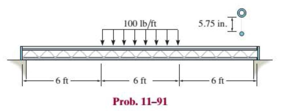
Chapter 11.4, Problem 91P
The simply supported truss is subjected to the central distributed load. Neglect the effect of the diagonal lacing and determine the absolute maximum bending stress in the truss. The top member is a pipe having an outer diameter of 1 in. and thickness of
Expert Solution & Answer
Want to see the full answer?
Check out a sample textbook solution
Students have asked these similar questions
The simply supported joist is used in the construction of a floor for a building. In order to keep the floor low with respect to the sill beams C and D, the ends of the joists are notched as shown. If the allowable shear stress is tallow = 350 psi and the allowable bending stress is sallow = 1500 psi, determine the height h that will cause the beam to reach both allowable stresses at the same time. Also, what load P causes this to happen? Neglect the stressconcentration at the notch.
The simply supported joist is used in the construction of a floor for a building. In order to keep the floor low with respect to the sill beams C and D, the ends of the joist are notched as shown. If the allowable shear stress is tallow = 350 psi and the allowable bending stress is s allow = 1700 psi, determine the smallest height h so that the beam will support a load of P = 600 lb. Also, will the entire joist safely support the load? Neglect the stress concentration at the notch.
The handle of the press is subjected to a force of 20 lb. Due to internal gearing, this causes the block to be subjected to a compressive force of 80 lb. Determine the normal-stress acting in the frame at points along the outside flanges A and B. Use the curved-beam formula to calculate the bending stress.
Chapter 11 Solutions
Statics and Mechanics of Materials (5th Edition)
Ch. 11.2 - In each case, the beam is subjected to the...Ch. 11.2 - In each ease, express the shear and moment...Ch. 11.2 - In each ease, express the shear and moment...Ch. 11.2 - In each ease, express the shear and moment...Ch. 11.2 - In each ease, express the shear and moment...Ch. 11.2 - Prob. 5FPCh. 11.2 - Prob. 6FPCh. 11.2 - In each ease, draw the shear and moment diagrams...Ch. 11.2 - Prob. 8FPCh. 11.2 - Prob. 1P
Ch. 11.2 - Draw the shear and moment diagrams for the beam,...Ch. 11.2 - Draw the shear and moment diagrams for the beam,...Ch. 11.2 - Express the shear and moment in terms of x for 0 ...Ch. 11.2 - Express the internal shear and moment in the...Ch. 11.2 - Prob. 6PCh. 11.2 - Express the internal shear and moment in terms of...Ch. 11.2 - Draw the shear and moment diagrams for the beam,...Ch. 11.2 - If the force applied to the handle of the load...Ch. 11.2 - Draw the shear and moment diagrams for the shaft....Ch. 11.2 - The crane is used to support the engine, which has...Ch. 11.2 - Prob. 12PCh. 11.2 - Draw the shear and moment diagrams for the beam....Ch. 11.2 - Draw the shear and moment diagrams for the beam....Ch. 11.2 - Members ABC and BD of the counter chair are...Ch. 11.2 - A reinforced concrete pier is used to support the...Ch. 11.2 - Draw the shear and moment diagrams for the beam...Ch. 11.2 - The industrial robot is held in the stationary...Ch. 11.2 - Determine the placement distance a of the roller...Ch. 11.2 - Prob. 20PCh. 11.2 - Draw the shear and moment diagrams for the beam....Ch. 11.2 - Draw the shear and moment diagrams for the...Ch. 11.2 - The 150-lb man sits in the center of the boat,...Ch. 11.2 - Prob. 24PCh. 11.2 - The footing supports the load transmitted by the...Ch. 11.2 - Prob. 26PCh. 11.2 - Prob. 27PCh. 11.2 - Draw the shear and moment diagrams for the beam....Ch. 11.2 - Draw the shear and moment diagrams for the beam....Ch. 11.2 - Prob. 30PCh. 11.2 - Prob. 31PCh. 11.2 - Prob. 32PCh. 11.2 - The shaft is supported by a smooth thrust bearing...Ch. 11.2 - Draw the shear and moment diagrams for the...Ch. 11.2 - Draw the shear and moment diagrams for the beam....Ch. 11.2 - Draw the shear and moment diagrams for the rod....Ch. 11.2 - Draw the shear and moment diagrams for the beam....Ch. 11.2 - Prob. 38PCh. 11.2 - Draw the shear and moment diagrams for the double...Ch. 11.2 - Draw the shear and moment diagrams for the simply...Ch. 11.2 - The compound beam is fixed at A, pin connected at...Ch. 11.2 - Draw the shear and moment diagrams for the...Ch. 11.2 - The compound beam is fixed at A, pin connected at...Ch. 11.2 - Draw the shear and moment diagrams for the beam....Ch. 11.2 - A short link at B is used to connect beams AB and...Ch. 11.2 - The truck is to be used to transport the concrete...Ch. 11.4 - Determine the moment of inertia of the cross...Ch. 11.4 - Prob. 3PPCh. 11.4 - In each case, show how the bending stress acts on...Ch. 11.4 - Prob. 5PPCh. 11.4 - If the beam is subjected to a bending moment of M...Ch. 11.4 - If the beam is subjected to a bending moment of M...Ch. 11.4 - If the beam is subjected to a bending moment of M...Ch. 11.4 - Prob. 12FPCh. 11.4 - If the beam is subjected to a bending moment of M...Ch. 11.4 - An A-36 steel strip has an allowable bending...Ch. 11.4 - Determine the moment M that will produce a maximum...Ch. 11.4 - Determine the maximum tensile and compressive...Ch. 11.4 - The beam is constructed from four pieces of wood,...Ch. 11.4 - The beam is constructed from four pieces of wood,...Ch. 11.4 - The beam is made from three boards nailed together...Ch. 11.4 - Prob. 53PCh. 11.4 - If the built-up beam is subjected to an internal...Ch. 11.4 - If the built-up beam is subjected to an internal...Ch. 11.4 - Prob. 56PCh. 11.4 - Determine the moment M that should be applied to...Ch. 11.4 - Prob. 58PCh. 11.4 - Prob. 59PCh. 11.4 - The beam is subjected to a moment of 15 kip ft....Ch. 11.4 - The beam is subjected to a moment of 15 kip ft....Ch. 11.4 - Prob. 62PCh. 11.4 - The steel shaft has a diameter of 2 in. It is...Ch. 11.4 - The beam is made of steel that has an allowable...Ch. 11.4 - Prob. 65PCh. 11.4 - Solve Prob. 11-65 if the moment M = 50 N m is...Ch. 11.4 - The shaft is supported by smooth journal bearings...Ch. 11.4 - Prob. 68PCh. 11.4 - Prob. 69PCh. 11.4 - The strut on the utility pole supports the cable...Ch. 11.4 - Prob. 71PCh. 11.4 - Prob. 72PCh. 11.4 - Determine the smallest allowable diameter of the...Ch. 11.4 - Prob. 74PCh. 11.4 - The shaft is supported by a thrust bearing at A...Ch. 11.4 - If the intensity of the load w = 15 kN/m,...Ch. 11.4 - If the allowable bending stress is allow = 150...Ch. 11.4 - The beam is subjected to the triangular...Ch. 11.4 - The beam has a rectangular cross section with b =...Ch. 11.4 - Determine the absolute maximum bending stress in...Ch. 11.4 - If the compound beam in Prob. 11-42 has a square...Ch. 11.4 - Prob. 82PCh. 11.4 - Prob. 83PCh. 11.4 - Determine, to the nearest millimeter, the smallest...Ch. 11.4 - Prob. 85PCh. 11.4 - Determine the absolute maximum bending stress in...Ch. 11.4 - Determine the smallest diameter of the shaft to...Ch. 11.4 - Prob. 88PCh. 11.4 - A log that is 2 ft in diameter is to be cut into a...Ch. 11.4 - The simply supported truss is subjected to the...Ch. 11.4 - Prob. 92PCh. 11.4 - Prob. 93PCh. 11.4 - Prob. 94PCh. 11.4 - The beam has the rectangular cross section shown....Ch. 11.5 - Determine the bending stress developed at corners...Ch. 11.5 - Prob. 15FPCh. 11.5 - Prob. 96PCh. 11.5 - Prob. 97PCh. 11.5 - Prob. 98PCh. 11.5 - Prob. 99PCh. 11.5 - Determine the bending stress at point A of the...Ch. 11.5 - The steel shaft is subjected to the two loads. If...Ch. 11.5 - Prob. 102PCh. 11.5 - Prob. 103PCh. 11.5 - Prob. 104PCh. 11 - Determine the shape factor for the wide-flange...Ch. 11 - The compound beam consists of two segments that...Ch. 11 - A shaft is made of a polymer having a parabolic...Ch. 11 - Determine the maximum bending stress in the handle...Ch. 11 - Determine the shear and moment in the beam as...Ch. 11 - A wooden beam has a square cross section as shown....Ch. 11 - Prob. 7RPCh. 11 - The strut has a square cross section a by a and is...
Knowledge Booster


Learn more about
Need a deep-dive on the concept behind this application? Look no further. Learn more about this topic, mechanical-engineering and related others by exploring similar questions and additional content below.Similar questions
- The overhang beam is constructed using two 2-in. by 4-in. pieces of wood braced as shown. If the allowable bending stress is sallow = 600 psi, determine the largest load P that can be applied. Also, determine the maximum spacing of nails, s, along the beam section AC if each nail can resist a shear force of 800 lb. Assume the beam is pin connected at A, B, and D. Neglect the axial force developed in the beam along DA.arrow_forwardThe axle of the freight train is subjected to loadings as shown below. The diameter of the axle is 137.5 mm. If it is supported by two journal bearings at C and D, determine the maximum bending stress. Include a FBD, SFD and BMD using either the section or graphical method. Draw a cross-section of the shaft and indicate the points of maximum tension and compression. A B 250 mm 100 kN 1500 mm- Answer 0= +98 MPa 250 mm 100 kNarrow_forwardThe eye hook has the dimensions shown. If it supports a cable loading of 800 lb, determine the maximum normal stress at section a–a and sketch the stress distribution acting over the cross section. Use the curved-beam formula to calculate the bending stress.arrow_forward
- A laminated spring Im long is built in 100 mm x 10 mm plates. If the spring is to carry a load of 10 kN at its centre, determine the number of plates required for the spring. Take allowable bending stress as 150 MPa.arrow_forwardbeam is supported by a roller and a hinge at its extremities. The 2 kN/m is loaded entirely on its 4 m length while 5 kN concentrated load is positioned 2 m from the left end of this beam. If the beam is 80 mm wide, determine the minimum height of the beam if the flexural stress is not to exceed 10 MPa.arrow_forwardA member having the dimensions shown is used to resist an internal bending moment of M kNm. Determine the maximum stress in the member if the moment is applied (a) about the z axis (as shown) (b) about the y axis. Sketch the stress distribution for each case. Take: M= 90 kNm A mm A= 200 mm B= 150 mm B mm Solution: The moment of inertia of the cross-section about z and y axes are I;-4 1 - AB³ 12 (10) m* I BA = (10) m*arrow_forward
- Q1/ A composite beam is made of wood and reinforced with steel strap located on its bottom side. It has the cross-sectional area shown in fig. if the beam is subjected to a bending moment of M=2kN.m, determine the normal stress at wood and steel. Take Ew=12Gpa and Est=200Gpa. 150mm Wood en 20mm Steel 150mmarrow_forwardQuestion 1: A member having the dimensions shown is used to resist an internal bending moment of M kNm. Determine the maximum stress in the member if the moment is applied (a) about the z axis (as shown) (b) about the y axis. Sketch the stress distribution for each case. Take: M= 98 kNm mm A= 208 mm B= 158 mm B mm Solution: The moment of inertia of the cross-section about z and y axes are 1 AB³ 12 |(10-) m* 1 ВАЗ — 12 I, |(10) m* = For the bending about z axis, c = m Mc O pax MPа Iz For the bending about y axis, c = m Mc MPа Iy max z MPa KN=M Omax Y MPa. M KN-M MPa O max Z Omax Y MPaarrow_forwardDetermine the internal normal force at point C, if F = 48 kN . Determine the shear force at point C Determine the bending moment at point Carrow_forward
- The pin is used to connect the three links together. Due to wear, the load is distributed over the top and bottom of the pin as shown on the free-body diagram. If the diameter of the pin is 0.40 in., determine the maximum bending stress on the cross-sectional area at the center section a–a. For the solution it is first necessary to determine the load intensities w1 and w2.arrow_forwardA strip of steel 3 mm thick and 35 mm wide is bent round a cylindrical drum 4 mm in diameter. Determine the maximum stress set up in the strip and the bending moment which has to be applied to bend the strip to this curvature (E = 200 GPa) A hollow short cast iron column has outside and inside diameters of 250 mm and 150 mm respectively. The column is subjected to an axial load applied at a distance of 60 mm from the center of the section. (a) Calculate the maximum safe load if the allowable stresses are 110 MPa compressive and 30 MPa tensile, calculate also the position of the NA.arrow_forwardThe beam is supported by a pin at point A and a roller at kN point B. A distributed load of W₁ = 8 - and an applied m force of F₁ = 12 kN are applied to the beam. The beam has an allowable bending stress of allow = 6 MPa. Neglect the weight and thickness of the beam. Take the origin for all functions to be at A., i.e. start at the left and go right. Must use positive sign convention for V and M. d3 1 d3 d1 W1 d1 B O h d2 F₁ Values for the figure are given in the following table. Note the figure may not be to scale. Dimensions for the whole beam Variable Value d₁ 4 m d₂ 2 marrow_forward
arrow_back_ios
SEE MORE QUESTIONS
arrow_forward_ios
Recommended textbooks for you
 Elements Of ElectromagneticsMechanical EngineeringISBN:9780190698614Author:Sadiku, Matthew N. O.Publisher:Oxford University Press
 Mechanics of Materials (10th Edition)Mechanical EngineeringISBN:9780134319650Author:Russell C. HibbelerPublisher:PEARSON
 Thermodynamics: An Engineering ApproachMechanical EngineeringISBN:9781259822674Author:Yunus A. Cengel Dr., Michael A. BolesPublisher:McGraw-Hill Education
 Control Systems EngineeringMechanical EngineeringISBN:9781118170519Author:Norman S. NisePublisher:WILEY
 Mechanics of Materials (MindTap Course List)Mechanical EngineeringISBN:9781337093347Author:Barry J. Goodno, James M. GerePublisher:Cengage Learning
 Engineering Mechanics: StaticsMechanical EngineeringISBN:9781118807330Author:James L. Meriam, L. G. Kraige, J. N. BoltonPublisher:WILEY
Elements Of Electromagnetics
Mechanical Engineering
ISBN:9780190698614
Author:Sadiku, Matthew N. O.
Publisher:Oxford University Press
Mechanics of Materials (10th Edition)
Mechanical Engineering
ISBN:9780134319650
Author:Russell C. Hibbeler
Publisher:PEARSON
Thermodynamics: An Engineering Approach
Mechanical Engineering
ISBN:9781259822674
Author:Yunus A. Cengel Dr., Michael A. Boles
Publisher:McGraw-Hill Education
Control Systems Engineering
Mechanical Engineering
ISBN:9781118170519
Author:Norman S. Nise
Publisher:WILEY
Mechanics of Materials (MindTap Course List)
Mechanical Engineering
ISBN:9781337093347
Author:Barry J. Goodno, James M. Gere
Publisher:Cengage Learning
Engineering Mechanics: Statics
Mechanical Engineering
ISBN:9781118807330
Author:James L. Meriam, L. G. Kraige, J. N. Bolton
Publisher:WILEY
BEARINGS BASICS and Bearing Life for Mechanical Design in 10 Minutes!; Author: Less Boring Lectures;https://www.youtube.com/watch?v=aU4CVZo3wgk;License: Standard Youtube License