
Fundamentals of Electric Circuits
6th Edition
ISBN: 9780078028229
Author: Charles K Alexander, Matthew Sadiku
Publisher: McGraw-Hill Education
expand_more
expand_more
format_list_bulleted
Concept explainers
Videos
Textbook Question
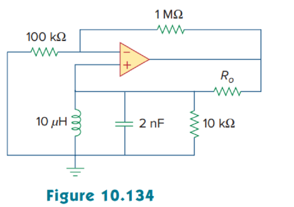
Chapter 10, Problem 92P
The oscillator circuit in Fig. 10.134 uses an ideal op amp.
- (a) Calculate the minimum value of Ro that will cause oscillation to occur.
- (b) Find the frequency of oscillation.
Expert Solution & Answer
Want to see the full answer?
Check out a sample textbook solution
Students have asked these similar questions
The given Oscillator,a) Draw the small sign model,b) Determine the oscillator frequency and oscillation condition.VDD: 8V Rp = 7006 Ω,Other Remaining Resistor, Inductance and Capacitor shipping you specify.
Q2) design a phase shift oscillator to produce an oscillation at 5 kHz with
an amplitude limited 5 peak to peak.
An ideal ac current source is applied to the input terminals of an amplifier, and the amplifier output voltage is 2 V rms. Then, a 2-kΩ resistance is placed in parallel with the current source and the amplifier input terminals, and the output voltage is 1.5 V rms. Determine the input resistance of the amplifier.
Chapter 10 Solutions
Fundamentals of Electric Circuits
Ch. 10.2 - Using nodal analysis, find v1 and v2 is in the...Ch. 10.2 - Calculate V1 and V2 in the circuit shown in Fig....Ch. 10.3 - Find Io in Fig. 10.8 using mesh analysis. Figure...Ch. 10.3 - Figure 10.11 For Practice Prob. 10.4. Calculate...Ch. 10.4 - Find current Io in the circuit of Fig. 10.8 using...Ch. 10.4 - Calculate vo in the circuit of Fig. 10.15 using...Ch. 10.6 - Determine the Norton equivalent of the circuit in...Ch. 10.7 - Find vo and io in the op amp circuit of Fig....Ch. 10.7 - Obtain the closed-loop gain and phase shift for...Ch. 10.8 - Use PSpice to obtain vo and io in the circuit of...
Ch. 10.8 - Obtain Vx and Ix in the circuit depicted in Fig....Ch. 10.9 - Determine the equivalent capacitance of the op amp...Ch. 10.9 - In the Wien-bridge oscillator circuit in Fig....Ch. 10 - The voltage Vo across the capacitor in Fig. 10.43...Ch. 10 - The value of the current Io in the circuit of Fig....Ch. 10 - Using nodal analysis, the value of Vo in the...Ch. 10 - In the circuit of Fig. 10.46, current i(t) is: (a)...Ch. 10 - Refer to the circuit in Fig. 10.47 and observe...Ch. 10 - For the circuit in Fig. 10.48, the Thevenin...Ch. 10 - In the circuit of Fig. 10.48, the Thevenin voltage...Ch. 10 - Refer to the circuit in Fig. 10.49. The Norton...Ch. 10 - Figure 10.49 For Review Questions 10.8 and 10.9....Ch. 10 - PSpice can handle a circuit with two independent...Ch. 10 - Determine i in the circuit of Fig. 10.50. Figure...Ch. 10 - Using Fig. 10.51, design a problem to help other...Ch. 10 - Determine vo in the circuit of Fig. 10.52. Figure...Ch. 10 - Compute vo(t) in the circuit of Fig. 10.53. Figure...Ch. 10 - Find io in the circuit of Fig. 10.54.Ch. 10 - Determine Vx in Fig. 10.55. Figure 10.55 For Prob....Ch. 10 - Use nodal analysis to find V in the circuit of...Ch. 10 - Use nodal analysis to find current io in the...Ch. 10 - Use nodal analysis to find vo in the circuit of...Ch. 10 - Use nodal analysis to find vo in the circuit of...Ch. 10 - Using nodal analysis, find io(t) in the circuit in...Ch. 10 - Using Fig. 10.61, design a problem to help other...Ch. 10 - Determine Vx in the circuit of Fig. 10.62 using...Ch. 10 - Calculate the voltage at nodes 1 and 2 in the...Ch. 10 - Solve for the current I in the circuit of Fig....Ch. 10 - Use nodal analysis to find Vx in the circuit shown...Ch. 10 - By nodal analysis, obtain current Io in the...Ch. 10 - Use nodal analysis to obtain Vo in the circuit of...Ch. 10 - Obtain Vo in Fig. 10.68 using nodal analysis.Ch. 10 - Refer to Fig. 10.69. If vs (t) = Vm sin t and vo...Ch. 10 - For each of the circuits in Fig. 10.70, find Vo/Vi...Ch. 10 - For the circuit in Fig. 10.71, determine Vo/Vs....Ch. 10 - Using nodal analysis obtain V in the circuit of...Ch. 10 - Design a problem to help other students better...Ch. 10 - Solve for io in Fig. 10.73 using mesh analysis....Ch. 10 - Use mesh analysis to find current io in the...Ch. 10 - Using mesh analysis, find I1 and I2 in the circuit...Ch. 10 - In the circuit of Fig. 10.76, determine the mesh...Ch. 10 - Using Fig. 10.77, design a problem help other...Ch. 10 - Use mesh analysis to find vo in the circuit of...Ch. 10 - Use mesh analysis to determine current Io in the...Ch. 10 - Determine Vo and Io in the circuit of Fig. 10.80...Ch. 10 - Compute I in Prob. 10.15 using mesh analysis....Ch. 10 - Use mesh analysis to find Io in Fig. 10.28 (for...Ch. 10 - Calculate Io in Fig. 10.30 (for Practice Prob....Ch. 10 - Compute Vo in the circuit of Fig. 10.81 using mesh...Ch. 10 - Use mesh analysis to find currents I1, I2, and I3...Ch. 10 - Using mesh analysis, obtain Io in the circuit...Ch. 10 - Find I1, I2, I3, and Ix in the circuit of Fig....Ch. 10 - Find io in the circuit shown in Fig. 10.85 using...Ch. 10 - Find vo for the circuit in Fig. 10.86, assuming...Ch. 10 - Using Fig. 10.87, design a problem to help other...Ch. 10 - Using the superposition principle, find ix in the...Ch. 10 - Use the superposition principle to obtain vx in...Ch. 10 - Use superposition to find i(t) in the circuit of...Ch. 10 - Solve for vo(t) in the circuit of Fig. 10.91 using...Ch. 10 - Determine io in the circuit of Fig. 10.92, using...Ch. 10 - Find io in the circuit of Fig. 10.93 using...Ch. 10 - Using source transformation, find i in the circuit...Ch. 10 - Using Fig. 10.95, design a problem to help other...Ch. 10 - Use source transformation to find Io in the...Ch. 10 - Use the concept of source transformation to find...Ch. 10 - Rework Prob. 10.7 using source transformation. Use...Ch. 10 - Find the Thevenin and Norton equivalent circuits...Ch. 10 - For each of the circuits in Fig. 10.99, obtain...Ch. 10 - Using Fig. 10.100, design a problem to help other...Ch. 10 - For the circuit depicted in Fig. 10.101, find the...Ch. 10 - Calculate the output impedance of the circuit...Ch. 10 - Find the Thevenin equivalent of the circuit in...Ch. 10 - Using Thevenins theorem, find vo in the circuit of...Ch. 10 - Obtain the Norton equivalent of the circuit...Ch. 10 - For the circuit shown in Fig. 10.107, find the...Ch. 10 - Using Fig. 10.108, design a problem to help other...Ch. 10 - At terminals a-b, obtain Thevenin and Norton...Ch. 10 - Find the Thevenin and Norton equivalent circuits...Ch. 10 - Find the Thevenin equivalent at terminals ab in...Ch. 10 - For the integrator shown in Fig. 10.112, obtain...Ch. 10 - Using Fig. 10.113, design a problem to help other...Ch. 10 - Find vo in the op amp circuit of Fig. 10.114....Ch. 10 - Compute io(t) in the op amp circuit in Fig. 10.115...Ch. 10 - If the input impedance is defined as Zin = Vs/Is,...Ch. 10 - Evaluate the voltage gain Av = Vo/Vs in the op amp...Ch. 10 - In the op amp circuit of Fig. 10.118, find the...Ch. 10 - Determine Vo and Io in the op amp circuit of Fig....Ch. 10 - Compute the closed-loop gain Vo/Vs for the op amp...Ch. 10 - Determine vo(t) in the op amp circuit in Fig....Ch. 10 - For the op amp circuit in Fig. 10.122, obtain Vo....Ch. 10 - Obtain vo(t) for the op amp circuit in Fig. 10.123...Ch. 10 - Use PSpice or MultiSim to determine Vo in the...Ch. 10 - Solve Prob. 10.19 using PSpice or MultiSim. Obtain...Ch. 10 - Use PSpice or MultiSim to find vo(t) in the...Ch. 10 - Obtain Vo in the circuit of Fig. 10.126 using...Ch. 10 - Using Fig. 10.127, design a problem to help other...Ch. 10 - Use PSpice or MultiSim to find V1, V2, and V3 in...Ch. 10 - Determine V1, V2, and V3 in the circuit of Fig....Ch. 10 - Use PSpice or MultiSim to find vo and io in the...Ch. 10 - The op amp circuit in Fig. 10.131 is called an...Ch. 10 - Figure 10.132 shows a Wien-bridge network. Show...Ch. 10 - Consider the oscillator in Fig. 10.133. (a)...Ch. 10 - The oscillator circuit in Fig. 10.134 uses an...Ch. 10 - Figure 10.135 shows a Colpitts oscillator. Show...Ch. 10 - Design a Colpitts oscillator that will operate at...Ch. 10 - Figure 10.136 shows a Hartley oscillator. Show...Ch. 10 - Refer to the oscillator in Fig. 10.137. (a) Show...
Knowledge Booster


Learn more about
Need a deep-dive on the concept behind this application? Look no further. Learn more about this topic, electrical-engineering and related others by exploring similar questions and additional content below.Similar questions
- 1) A Twin-T notch oscillator have a variable capacitors and fixed resistors. If the notch frequency should be 1 kHz, a. Determine what value should the capacitor be tuned if the values of R is 2 k. b. Using the same value of R, If the capacitors were tune to 100 nF, what will be the notch frequency? ?) Wien bridge oscillator uses the following components, R1 = 150 kn, R2 = 220 kn, C1 =arrow_forwardG) build a low-frequency square wave generator using a basic comparator having a frequency of 1kHz and a 30% duty cycle. Explain the principle of operation and the type of feedback of the op-amp. What is the advantage of this circuit? H) Build a phase-shift oscillator using, C=1µF and +10V power supply to produce a 10 kHz sinusoidal waveform. Generate your plots and compare output results. Highlight any discrepancies and discuss what happens if we want to increase the frequency to 100 kHz. I) Build a Colpitts oscillator producing 100kHz Discuss its advantage over RC oscillators. How can you modify the circuit to include a crystal in your circuit? What is a typical application of such an oscillator? Discuss the advantages and disadvantages of crystal oscillators.arrow_forwardA silicon photodiode is connected to an op-amp as indicated. Under an illuminance of 500 lux, the photocurrent Ip is 80 nA. I R = 1MQ w out Write down the values of 11, 12 and Ip. From these values, deduce the output voltage. Briefly describe how this circuit works. c) Will this circuit work under sunlight? The illuminance of sunlight is about 100,000 lux. You may assume the photocurrent respond linearly with incident light flux, and the op-amp is powered between 9V alkaline cell. (i.e., V+ = 9V, V¯ at ground).arrow_forward
- Build a Colpitts oscillator producing 100kHz Discuss its advantage over RC oscillators. How can you modify the circuit to include a crystal in you circuit. What is a typical application of such an oscillator? Discuss the advantages and disadvantages of crystal oscillators.arrow_forwardAnswer the following with illustration and solutions. 1.) If an electronic system produces an 32v output voltage when 6.5v signals is applied, calculate the decibel value of the system output voltage. These is the example that might help.. see the picture below.arrow_forwardThe circuit below shows an oscillator. a. Name the type of oscillator b. Should the amplifier be inverting or non-inverting? Explain why. c. For the circuit to oscillate, what is the minimum gain the amplifier could have? ANSWER: -5 d. What value should the inductor have if the operating frequency is to be 5MHZ? ANSWER: 60.78µH 100 pF 200 pF 20 pFarrow_forward
- Q3) for the RC oscillator circuit shown with = 1 nF and R =1 KQ answer the following: 1. Find the value of Rf and Ri to start oscillation 2. What is the phase shift of each RC-section if there is 6 RC-sections 3. For the same frequency of oscillation design another RC oscillator circuit using non-inverting configuration of Op-amp R; Ор-amparrow_forwardA Voltage-Controlled Oscillator has a linear response of 2.5MHz/volt. It covers a frequency range of 25MHz. The tuning range starts at 3volts, where the VCO frequency is 50MHz. The output frequer increases as the tuning voltage is increased. What tuning voltage is required to obtain a VCO frequency of 65MHz?arrow_forwardL C For the oscillator circuit shown: a) Derivet oscillation conditions? b) Calculate the frequency of oscillation and the minimum value of R3, required to sustain oscillation. L=1mH, C = 0.1μF, R₂ = 10k and R = R₁ = 1k0 -1 www K www 33 R₁ R3 www Find R₂ ww .V₁₂ Activate Windowsarrow_forward
- ١-Draw a Wien bridge oscillator Write the frequency of oscillation Write the condition of oscillation( the relation between Rf and Ri )What is the voltage gain condition for the oscillator to stat-up V-Design an ADC circuit using OPAMP ( using weighted resistors)arrow_forwardFor the given circuit, assume the op amp to be ideal. R = 10 kN, C = 16 nF. a) Find L(s). L(jw). b) Prove that the frequency of oscillation is wo = 1/RC( c) Detemine the condition for oscillation.arrow_forward(a) Explain how a Phase Shift Oscillator differs from Colpitts Oscillator in operation. (b) Design a Wein Bridge Oscillator using Op-Amp with a resonant frequency, fr = 3.2KHZ. Let +Vcc = 15 V, -Vee =-15 V and C= 681F. Draw the circuit diagram and label all components. Use standard resistance values.arrow_forward
arrow_back_ios
SEE MORE QUESTIONS
arrow_forward_ios
Recommended textbooks for you
 Introductory Circuit Analysis (13th Edition)Electrical EngineeringISBN:9780133923605Author:Robert L. BoylestadPublisher:PEARSON
 Delmar's Standard Textbook Of ElectricityElectrical EngineeringISBN:9781337900348Author:Stephen L. HermanPublisher:Cengage Learning
 Programmable Logic ControllersElectrical EngineeringISBN:9780073373843Author:Frank D. PetruzellaPublisher:McGraw-Hill Education
 Fundamentals of Electric CircuitsElectrical EngineeringISBN:9780078028229Author:Charles K Alexander, Matthew SadikuPublisher:McGraw-Hill Education
 Electric Circuits. (11th Edition)Electrical EngineeringISBN:9780134746968Author:James W. Nilsson, Susan RiedelPublisher:PEARSON
 Engineering ElectromagneticsElectrical EngineeringISBN:9780078028151Author:Hayt, William H. (william Hart), Jr, BUCK, John A.Publisher:Mcgraw-hill Education,
Introductory Circuit Analysis (13th Edition)
Electrical Engineering
ISBN:9780133923605
Author:Robert L. Boylestad
Publisher:PEARSON
Delmar's Standard Textbook Of Electricity
Electrical Engineering
ISBN:9781337900348
Author:Stephen L. Herman
Publisher:Cengage Learning
Programmable Logic Controllers
Electrical Engineering
ISBN:9780073373843
Author:Frank D. Petruzella
Publisher:McGraw-Hill Education
Fundamentals of Electric Circuits
Electrical Engineering
ISBN:9780078028229
Author:Charles K Alexander, Matthew Sadiku
Publisher:McGraw-Hill Education
Electric Circuits. (11th Edition)
Electrical Engineering
ISBN:9780134746968
Author:James W. Nilsson, Susan Riedel
Publisher:PEARSON
Engineering Electromagnetics
Electrical Engineering
ISBN:9780078028151
Author:Hayt, William H. (william Hart), Jr, BUCK, John A.
Publisher:Mcgraw-hill Education,
Current Divider Rule; Author: Neso Academy;https://www.youtube.com/watch?v=hRU1mKWUehY;License: Standard YouTube License, CC-BY