
Fundamentals of Electric Circuits
6th Edition
ISBN: 9780078028229
Author: Charles K Alexander, Matthew Sadiku
Publisher: McGraw-Hill Education
expand_more
expand_more
format_list_bulleted
Concept explainers
Videos
Textbook Question
Chapter 10, Problem 20P
Refer to Fig. 10.69. If vs (t) = Vm sin ωt and vo (t) = A sin (ωt + φ) derive the expressions for A and φ.
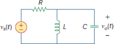
Figure 10.69
Expert Solution & Answer
Want to see the full answer?
Check out a sample textbook solution
Students have asked these similar questions
1.) In a linear circuit, the voltage source is us = 12 sin(10°t+ 24)V
(a) What is the angular frequency of the voltage?
(b) What is the frequency of the source?
(c) Find the period of the voltage.
20) With an input sinusoid as shown, determine the yvo(t). Another way of saying this
is what is v.(t), where L=1.0 mH
20).
Vs (t) (*
10 μF
Vout (1)
v<(1) = 50 sin100t V
a) 50 sin(100t) b) 50 sin(100t-90 deg)
c) 50 volt DC
d) 50*1.41* sin(100t-30 deg)
Write a Matlab code to sketch using plot function, y(t)=3 sin(t) for 3 periods
Chapter 10 Solutions
Fundamentals of Electric Circuits
Ch. 10.2 - Using nodal analysis, find v1 and v2 is in the...Ch. 10.2 - Calculate V1 and V2 in the circuit shown in Fig....Ch. 10.3 - Find Io in Fig. 10.8 using mesh analysis. Figure...Ch. 10.3 - Figure 10.11 For Practice Prob. 10.4. Calculate...Ch. 10.4 - Find current Io in the circuit of Fig. 10.8 using...Ch. 10.4 - Calculate vo in the circuit of Fig. 10.15 using...Ch. 10.6 - Determine the Norton equivalent of the circuit in...Ch. 10.7 - Find vo and io in the op amp circuit of Fig....Ch. 10.7 - Obtain the closed-loop gain and phase shift for...Ch. 10.8 - Use PSpice to obtain vo and io in the circuit of...
Ch. 10.8 - Obtain Vx and Ix in the circuit depicted in Fig....Ch. 10.9 - Determine the equivalent capacitance of the op amp...Ch. 10.9 - In the Wien-bridge oscillator circuit in Fig....Ch. 10 - The voltage Vo across the capacitor in Fig. 10.43...Ch. 10 - The value of the current Io in the circuit of Fig....Ch. 10 - Using nodal analysis, the value of Vo in the...Ch. 10 - In the circuit of Fig. 10.46, current i(t) is: (a)...Ch. 10 - Refer to the circuit in Fig. 10.47 and observe...Ch. 10 - For the circuit in Fig. 10.48, the Thevenin...Ch. 10 - In the circuit of Fig. 10.48, the Thevenin voltage...Ch. 10 - Refer to the circuit in Fig. 10.49. The Norton...Ch. 10 - Figure 10.49 For Review Questions 10.8 and 10.9....Ch. 10 - PSpice can handle a circuit with two independent...Ch. 10 - Determine i in the circuit of Fig. 10.50. Figure...Ch. 10 - Using Fig. 10.51, design a problem to help other...Ch. 10 - Determine vo in the circuit of Fig. 10.52. Figure...Ch. 10 - Compute vo(t) in the circuit of Fig. 10.53. Figure...Ch. 10 - Find io in the circuit of Fig. 10.54.Ch. 10 - Determine Vx in Fig. 10.55. Figure 10.55 For Prob....Ch. 10 - Use nodal analysis to find V in the circuit of...Ch. 10 - Use nodal analysis to find current io in the...Ch. 10 - Use nodal analysis to find vo in the circuit of...Ch. 10 - Use nodal analysis to find vo in the circuit of...Ch. 10 - Using nodal analysis, find io(t) in the circuit in...Ch. 10 - Using Fig. 10.61, design a problem to help other...Ch. 10 - Determine Vx in the circuit of Fig. 10.62 using...Ch. 10 - Calculate the voltage at nodes 1 and 2 in the...Ch. 10 - Solve for the current I in the circuit of Fig....Ch. 10 - Use nodal analysis to find Vx in the circuit shown...Ch. 10 - By nodal analysis, obtain current Io in the...Ch. 10 - Use nodal analysis to obtain Vo in the circuit of...Ch. 10 - Obtain Vo in Fig. 10.68 using nodal analysis.Ch. 10 - Refer to Fig. 10.69. If vs (t) = Vm sin t and vo...Ch. 10 - For each of the circuits in Fig. 10.70, find Vo/Vi...Ch. 10 - For the circuit in Fig. 10.71, determine Vo/Vs....Ch. 10 - Using nodal analysis obtain V in the circuit of...Ch. 10 - Design a problem to help other students better...Ch. 10 - Solve for io in Fig. 10.73 using mesh analysis....Ch. 10 - Use mesh analysis to find current io in the...Ch. 10 - Using mesh analysis, find I1 and I2 in the circuit...Ch. 10 - In the circuit of Fig. 10.76, determine the mesh...Ch. 10 - Using Fig. 10.77, design a problem help other...Ch. 10 - Use mesh analysis to find vo in the circuit of...Ch. 10 - Use mesh analysis to determine current Io in the...Ch. 10 - Determine Vo and Io in the circuit of Fig. 10.80...Ch. 10 - Compute I in Prob. 10.15 using mesh analysis....Ch. 10 - Use mesh analysis to find Io in Fig. 10.28 (for...Ch. 10 - Calculate Io in Fig. 10.30 (for Practice Prob....Ch. 10 - Compute Vo in the circuit of Fig. 10.81 using mesh...Ch. 10 - Use mesh analysis to find currents I1, I2, and I3...Ch. 10 - Using mesh analysis, obtain Io in the circuit...Ch. 10 - Find I1, I2, I3, and Ix in the circuit of Fig....Ch. 10 - Find io in the circuit shown in Fig. 10.85 using...Ch. 10 - Find vo for the circuit in Fig. 10.86, assuming...Ch. 10 - Using Fig. 10.87, design a problem to help other...Ch. 10 - Using the superposition principle, find ix in the...Ch. 10 - Use the superposition principle to obtain vx in...Ch. 10 - Use superposition to find i(t) in the circuit of...Ch. 10 - Solve for vo(t) in the circuit of Fig. 10.91 using...Ch. 10 - Determine io in the circuit of Fig. 10.92, using...Ch. 10 - Find io in the circuit of Fig. 10.93 using...Ch. 10 - Using source transformation, find i in the circuit...Ch. 10 - Using Fig. 10.95, design a problem to help other...Ch. 10 - Use source transformation to find Io in the...Ch. 10 - Use the concept of source transformation to find...Ch. 10 - Rework Prob. 10.7 using source transformation. Use...Ch. 10 - Find the Thevenin and Norton equivalent circuits...Ch. 10 - For each of the circuits in Fig. 10.99, obtain...Ch. 10 - Using Fig. 10.100, design a problem to help other...Ch. 10 - For the circuit depicted in Fig. 10.101, find the...Ch. 10 - Calculate the output impedance of the circuit...Ch. 10 - Find the Thevenin equivalent of the circuit in...Ch. 10 - Using Thevenins theorem, find vo in the circuit of...Ch. 10 - Obtain the Norton equivalent of the circuit...Ch. 10 - For the circuit shown in Fig. 10.107, find the...Ch. 10 - Using Fig. 10.108, design a problem to help other...Ch. 10 - At terminals a-b, obtain Thevenin and Norton...Ch. 10 - Find the Thevenin and Norton equivalent circuits...Ch. 10 - Find the Thevenin equivalent at terminals ab in...Ch. 10 - For the integrator shown in Fig. 10.112, obtain...Ch. 10 - Using Fig. 10.113, design a problem to help other...Ch. 10 - Find vo in the op amp circuit of Fig. 10.114....Ch. 10 - Compute io(t) in the op amp circuit in Fig. 10.115...Ch. 10 - If the input impedance is defined as Zin = Vs/Is,...Ch. 10 - Evaluate the voltage gain Av = Vo/Vs in the op amp...Ch. 10 - In the op amp circuit of Fig. 10.118, find the...Ch. 10 - Determine Vo and Io in the op amp circuit of Fig....Ch. 10 - Compute the closed-loop gain Vo/Vs for the op amp...Ch. 10 - Determine vo(t) in the op amp circuit in Fig....Ch. 10 - For the op amp circuit in Fig. 10.122, obtain Vo....Ch. 10 - Obtain vo(t) for the op amp circuit in Fig. 10.123...Ch. 10 - Use PSpice or MultiSim to determine Vo in the...Ch. 10 - Solve Prob. 10.19 using PSpice or MultiSim. Obtain...Ch. 10 - Use PSpice or MultiSim to find vo(t) in the...Ch. 10 - Obtain Vo in the circuit of Fig. 10.126 using...Ch. 10 - Using Fig. 10.127, design a problem to help other...Ch. 10 - Use PSpice or MultiSim to find V1, V2, and V3 in...Ch. 10 - Determine V1, V2, and V3 in the circuit of Fig....Ch. 10 - Use PSpice or MultiSim to find vo and io in the...Ch. 10 - The op amp circuit in Fig. 10.131 is called an...Ch. 10 - Figure 10.132 shows a Wien-bridge network. Show...Ch. 10 - Consider the oscillator in Fig. 10.133. (a)...Ch. 10 - The oscillator circuit in Fig. 10.134 uses an...Ch. 10 - Figure 10.135 shows a Colpitts oscillator. Show...Ch. 10 - Design a Colpitts oscillator that will operate at...Ch. 10 - Figure 10.136 shows a Hartley oscillator. Show...Ch. 10 - Refer to the oscillator in Fig. 10.137. (a) Show...
Knowledge Booster


Learn more about
Need a deep-dive on the concept behind this application? Look no further. Learn more about this topic, electrical-engineering and related others by exploring similar questions and additional content below.Similar questions
- 10:55 BYV 2.00 Yo 49 (48) KB/S Two coils are A and B ar : Editing 9/7/21 10:55 AM Two coils are A and B are connected in series to a supply of 230V, 50HZ. Coil A has an inductance of 0.2H and a resistance of 20 Q, and coil B has an inductance of 0.05H and a resistance of 60 Q. Calculate the current and its phase angle relative to the supply voltage. Also determine the voltage across each coil. |arrow_forward2) A current source in a linear circuit has i(t) = 15 cos(25nt + 25º) A. a) What is the amplitude of the current? b) What is the angular frequency? c) Find the frequency of the current d) Calculate i, at t= 2 msarrow_forwardPleasearrow_forward
- Calculate current of inductor and voltage of capacitor in transient state after turning on the switch in the circuit of Fig. 10.25. Assume: R=5Ω, C=100μF, L=1H, e1(t)=10V, e2(t)=10V.arrow_forwardWrite an expression for the output voltage for the circuit as shown if υ1 = 0.5 sin 2000πt, and υ2 is generated by the circuit as shown with υ3 = 0.5 sin 10,000πt? Assume VCC = −VEE = 10 V, IEE = 500 μA, R1 = R3 = 2 kΩ, and R = 10 kΩ.arrow_forward(b) A series RLC circuit with L=160 mH. C= 100 µF, and R = (X+10)N is connected to a sinusoidal voltage V (t) = (X+10)V sinot, with o = 200 rad/s. X =2 i) Calculate the impedance of the circuit. ii) Let the current at any instant in the circuit be I (t) = I, sin (@t -o). Find Ia. iii) What is the phase o?arrow_forward
- Solve for the sinusoidal voltage and currents, v(t) and i(t), on the given circuit. v(t) V i(t) mA i(t) 500 Ω F 1 μF i, = 50cos(2000t) mA 500 mH + v(t)arrow_forwardThe voltage and current of an element are i(t) = 3.cos(1000t + 10°) V(t) = 6.cos(1000t – 80°) The element is Select one: a. resistor and capacitor (R and C) b. Сарacitor C c. resistor R d. Inductor Larrow_forward10.25 For the following RC circuit: + e - 56 μF 22 V 7 kl a) Determine the time constant of the circuit when the switch is thrown into position 1. b) Find the mathematical expression for the voltage across the capacitor and the current after the switch is thrown into position 1. C) Determine the magnitude of the voltage vC and the current iC the instant the switch is thrown into position 2 at t=1s. d) Determine the mathematical expression for the voltage vC and the current iC for the discharge phase e) Plot the waveforms of vC and iC for the period of time extending from 0 to 2 seconds from when the switch was thrown into position 1arrow_forward
- Q. For the 10 V amplitude, 1 Hz triangular input (vi), calculate and plot the output of the circuit given on the right (v.), indicating the relevant values on the axis. (Show your calculations). 10 V t/2 -10 V + 50 ΚΩ 7 Varrow_forward1.→ Transform the following circuit to the frequency domain and draw the frequency domain circuit. Calculate the phasor current I and then determine the current i(t) in the time domain. Show the units in your answer. i(t) v(t) = 120 sin (3771 + 60°) V 50 μF 2002 40 mHarrow_forwardA voltage of v(t) = 4.7 cos (24 t - 42°) Vis applied across a capacitor C = 9.3 mF as shown. What is the magnitude of the current phasor through the capacitor? i(t) с - v(t) Please enter your answer in Amps (A), to 3 significant figures below.arrow_forward
arrow_back_ios
SEE MORE QUESTIONS
arrow_forward_ios
Recommended textbooks for you
 Delmar's Standard Textbook Of ElectricityElectrical EngineeringISBN:9781337900348Author:Stephen L. HermanPublisher:Cengage Learning
Delmar's Standard Textbook Of Electricity
Electrical Engineering
ISBN:9781337900348
Author:Stephen L. Herman
Publisher:Cengage Learning
Nodal Analysis for Circuits Explained; Author: Engineer4Free;https://www.youtube.com/watch?v=f-sbANgw4fo;License: Standard Youtube License