Concept explainers
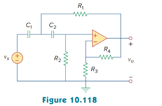
In the op amp circuit of Fig. 10.118, find the closed-loop gain and phase shift of the output voltage with respect to the input voltage if C1 = C2 = 1 nF, R1 = R2 = 100 kΩ, R3 = 20 kΩ R4 = 40 kΩ and ω = 2000 rad/s.

Calculate the closed-loop gain and phase shift of the output voltage of the op amp circuit in Figure 10.118 using MATLAB.
Answer to Problem 75P
The closed-loop gain and phase shift of the output voltage are
Explanation of Solution
Given data:
Refer to Figure 10.118 in the textbook for op amp circuit.
The value of angular frequency
Formula used:
Write the expression to calculate impedance of the capacitor.
Here,
Calculation:
Let us assume that source voltage
Substitute
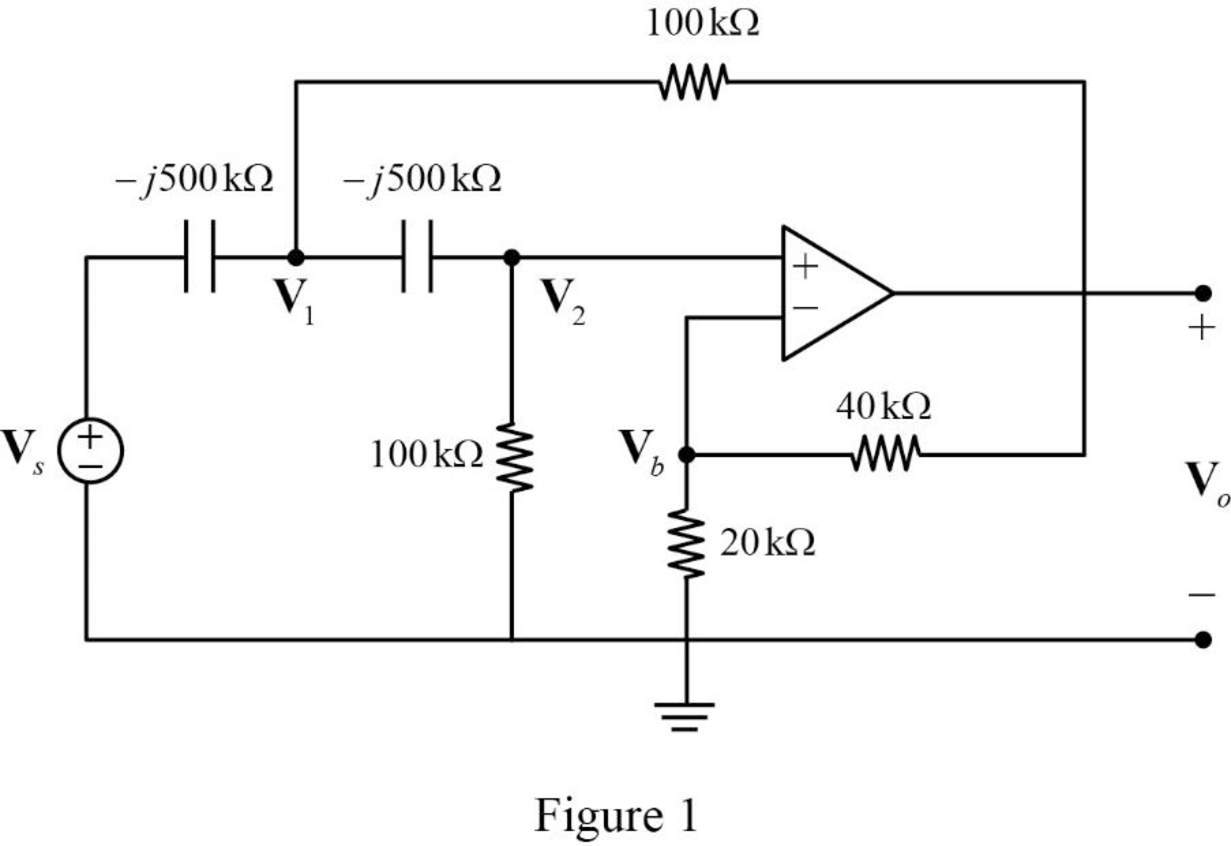
The frequency domain representation of given figure is shown in Figure 1.

Apply Kirchhoff’s current law at node
Substitute
Apply Kirchhoff’s current law at node
Apply voltage division rule at node
According to the properties of ideal op amp, the voltage at the input of the non-inverting terminal of the op amp is equal to the voltage at the input of the inverting terminal. Hence,
Substitute equation (5) in (2).
Substitute equation (5) in (3).
Represent the equations (6) and (7) in matrix form.
The MATLAB code to solve equation (8) is shown below.
A = [1+0.4*i -1-0.0667*i; 1 -0.3333+1.6667*i];
b = [2*i; 0];
x = A\b
The MATLAB result is shown below.
x =
-0.4166 + 2.0833i -1.2499 - 0.0000i
The polar representation of obtained results is shown below.
Write the expression for closed loop gain.
Substitute
Conclusion:
Thus, the closed-loop gain and phase shift of the output voltage are
Want to see more full solutions like this?
Chapter 10 Solutions
Fundamentals of Electric Circuits
- 2. During + input cycle, it has an output signal voltage, at the negative input cycle, the output experiences a negative current surge at the inductor and causes the circuit to explode. What could be wrong in the circuit? Explain. Q1 R1 1kQ D1 V2 1kHz 5V L1 V1 1mH 12Varrow_forwardTyping solution only please and rightarrow_forwardThe components in the circuit shown below are ideal. If the op-amp is in positive feedback and the input voltage V, is a sine wave of amplitude 1 V, the output voltage V, is 1 kΩ ww +5 V 1 V 1 k2 V,o WW -1 V -5 V (a) a square wave of 5 V amplitude (b) an inverted sine wave of 1 V amplitude (c) a non-inverted sine wave of 2 V amplitude (d) a constant of either +5 or -5 Varrow_forward
- Solve it quickly pleasearrow_forwardQ2) design a wien bridge to produce an output sinusoid that can be adjusted from 400 Hz to 100 kHz assuming a capacitor equal to 0.01uF.arrow_forwardThe behavior of oscillator is described by Olong periods of dissipation followed by short impulses Oshort periods of dissipation followed by short impulses Olong periods of dissipation followed by long impulses ONone of the abovearrow_forward
 Introductory Circuit Analysis (13th Edition)Electrical EngineeringISBN:9780133923605Author:Robert L. BoylestadPublisher:PEARSON
 Delmar's Standard Textbook Of ElectricityElectrical EngineeringISBN:9781337900348Author:Stephen L. HermanPublisher:Cengage Learning
 Programmable Logic ControllersElectrical EngineeringISBN:9780073373843Author:Frank D. PetruzellaPublisher:McGraw-Hill Education
 Fundamentals of Electric CircuitsElectrical EngineeringISBN:9780078028229Author:Charles K Alexander, Matthew SadikuPublisher:McGraw-Hill Education
 Electric Circuits. (11th Edition)Electrical EngineeringISBN:9780134746968Author:James W. Nilsson, Susan RiedelPublisher:PEARSON
 Engineering ElectromagneticsElectrical EngineeringISBN:9780078028151Author:Hayt, William H. (william Hart), Jr, BUCK, John A.Publisher:Mcgraw-hill Education,


