
Concept explainers
Videos
Use nodal analysis to find vo in the circuit of Fig. 10.58.
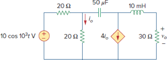
Figure 10.58
Find the voltage
Answer to Problem 9P
The value of voltage
Explanation of Solution
Given data:
Refer Figure 10.58 in the textbook for nodal analysis.
Formula used:
Write the expression to calculate impedance of the inductor.
Here,
Write the expression to calculate impedance of the capacitor.
Here,
Write the general representation of sinusoidal function.
Here,
Write the general expression to phasor transform of sinusoidal function from time domain to frequency domain.
Here,
Write the polar form representation of frequency domain.
Calculation:
Comparing given source voltage
Substitute
Substitute
Substitute
The frequency domain representation of given figure with the representation of node voltage is shown in Figure 1.
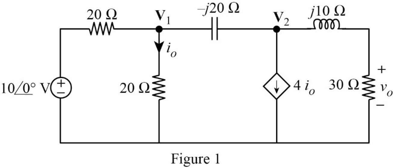
Apply Kirchhoff’s current law at node
Simplify the equation as follows.
Apply Kirchhoff’s current law at node
From Figure 1, write the expression for current
Substitute equation (7) in (6).
Simplify the equation as follows.
MATLAB Code:
Solve the two linear equations (5) and (8) using MATLAB to find the node voltage.
syms v1 v2
eq1 = (2 + 1*1i)*v1 +(-1*1i)*v2 == 10;
eq2 = (4 +(-1*1i))*v1 +(0.6 + 0.8*1i)*v2 == 0;
sol = solve([eq1, eq2], [v1, v2]);
val1 = sol.v1;
val2 = sol.v2;
v1real=real(val1);
v1imag=imag(val1);
v2real=real(val2);
v2imag=imag(val2);
v1=sprintf('%.3f + %.3fi V', v1real, v1imag);
v2=sprintf('%.3f + %.3fi V', v2real, v2imag)
The command window output:
v2 = '0.149 + 6.485i V'
From Figure 1, write the expression for
Substitute
Represent the voltage in time domain.
Conclusion:
Therefore, the value of voltage
Want to see more full solutions like this?
Chapter 10 Solutions
Fundamentals of Electric Circuits


- The oscillator circuit in Fig. 10.134 uses an ideal op amp. (a) Calculate the minimum value of R, that will cause oscillation to occur. (b) Find the frequency of oscillation. 1 M2 100 k2 ww R. 10 μΗ 2 nF 10 k2 wwarrow_forward10.23. Draw the block diagrams of both the direct forms I and II simulation diagrams for the systems with the following difference equations: (a) 2y[n]y[n 1] + 4y[n-2] = 5x[n] (b) 1 3]arrow_forward63. Use phasors and nodal analysis on the circuit of Fig. 10.65 to find V2. j3 0 5/90 A (* 30 O 10/0 Aarrow_forward
- 10.4 Find the -1/4 system function for the following structure. + -5/2arrow_forwardFigure 1090 For Prob. 1047. 10.48 Find i, in the circuit in Fig. 10.91 y superposition. A 10.: in the 50 cos 20007 V 0s(2t - 60°) V 2 sin 40001 A 10.5 Figure 1091 oarrow_forwardDetermine the Thevenin equivalent of the circuit in Fig. 10. 27 as seen from terminals a-b. 82 j42 ll ww o a -j22 5/0° A 0.2V 42arrow_forward
- 67. Use mesh analysis to find i,(t) in the circuit shown in Fig. 10.68. - - 75.96)A 0.04 H 10 cos 100r V 0.04 Farrow_forwardCalculate current of inductor and voltage of capacitor in transient state after turning on the switch in the circuit of Fig. 10.25. Assume: R=5Ω, C=100μF, L=1H, e1(t)=10V, e2(t)=10V.arrow_forward(ACADEMIC) 8205828page%3D1 The equivalent resistance RAR (in the figure) is: A O 62. 10. BO 10. 12. b. not possible to compute without Y to Delta conversion. C. bere to search S3一4arrow_forward
- Calculate Vo in the circuit of Fig. 10.15 using the superposition theorem. 8Ω ww 50 sin 5t V + 0.2 F 1 H 4 cos 10t A llarrow_forwardCalculate V₁ and V2 in the circuit shown in Fig. 10.6. 100/60° V 42 www + 75/0° V(+ j4 Ω -j10 ΖΩ Figure 10.6 For Practice Prob. 10.2.arrow_forwardIm:_,m 10.70 For Prob. 1 g8Q Jj6Q 40 j5Q WWW—T WWA—T + + 4£45° A VIS 21Qe i 2V, ==-jlQ -2Q =V, Figure 10.67 For Prob. 10.18.arrow_forward
 Introductory Circuit Analysis (13th Edition)Electrical EngineeringISBN:9780133923605Author:Robert L. BoylestadPublisher:PEARSON
 Delmar's Standard Textbook Of ElectricityElectrical EngineeringISBN:9781337900348Author:Stephen L. HermanPublisher:Cengage Learning
 Programmable Logic ControllersElectrical EngineeringISBN:9780073373843Author:Frank D. PetruzellaPublisher:McGraw-Hill Education
 Fundamentals of Electric CircuitsElectrical EngineeringISBN:9780078028229Author:Charles K Alexander, Matthew SadikuPublisher:McGraw-Hill Education
 Electric Circuits. (11th Edition)Electrical EngineeringISBN:9780134746968Author:James W. Nilsson, Susan RiedelPublisher:PEARSON
 Engineering ElectromagneticsElectrical EngineeringISBN:9780078028151Author:Hayt, William H. (william Hart), Jr, BUCK, John A.Publisher:Mcgraw-hill Education,