
Fundamentals of Electric Circuits
6th Edition
ISBN: 9780078028229
Author: Charles K Alexander, Matthew Sadiku
Publisher: McGraw-Hill Education
expand_more
expand_more
format_list_bulleted
Videos
Textbook Question
Chapter 10, Problem 77P
Compute the closed-loop gain Vo/Vs for the op amp circuit of Fig. 10.120.
Figure 10.120
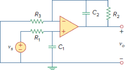
syms Vs W R1 R2 R3 C1 C2
V1=Vs/(1+1i*w*R1*C1);
Vo= (1 +1/((R3/R2) + 1i*C2*R3))*V1
Vo =
Expert Solution & Answer
Want to see the full answer?
Check out a sample textbook solution
Students have asked these similar questions
Problem 05.040 - Inverting summing amplifier
Referring to the circuit given below, determine Vo in terms of V₁ and V₂ if R = 30 2.
200 ΚΩ
100 ΚΩ
www
www
V₁
Vo = -(1
V₂
100 ΚΩ
www
]) V₁-([
10 92
ww
R
In the circuit given in the figure, β = 100, r0 = 40 kΩ, RB = 360 kΩ, RC = 3.3 kΩ, RE = 220 Ω, Rs = 0.5 kΩ and RL = 12.2 kΩ. Accordingly, find the voltage gain (Vout/Vin) of the circuit.NOTE-1: The output impedance of the transistor r0 will be taken into account in the calculations.NOTE-2: Capacitors are negligible at midband frequency.NOTE-3: The applied ac voltage has an amplitude of 10 mV and a frequency of 1 kHz.
For the given circuit, assume the op amp to be ideal. R = 10 kN, C =
16 nF.
a) Find L(s). L(jw).
b) Prove that the frequency of oscillation is wo = 1/RC(
c) Detemine the condition for oscillation.
Chapter 10 Solutions
Fundamentals of Electric Circuits
Ch. 10.2 - Using nodal analysis, find v1 and v2 is in the...Ch. 10.2 - Calculate V1 and V2 in the circuit shown in Fig....Ch. 10.3 - Find Io in Fig. 10.8 using mesh analysis. Figure...Ch. 10.3 - Figure 10.11 For Practice Prob. 10.4. Calculate...Ch. 10.4 - Find current Io in the circuit of Fig. 10.8 using...Ch. 10.4 - Calculate vo in the circuit of Fig. 10.15 using...Ch. 10.6 - Determine the Norton equivalent of the circuit in...Ch. 10.7 - Find vo and io in the op amp circuit of Fig....Ch. 10.7 - Obtain the closed-loop gain and phase shift for...Ch. 10.8 - Use PSpice to obtain vo and io in the circuit of...
Ch. 10.8 - Obtain Vx and Ix in the circuit depicted in Fig....Ch. 10.9 - Determine the equivalent capacitance of the op amp...Ch. 10.9 - In the Wien-bridge oscillator circuit in Fig....Ch. 10 - The voltage Vo across the capacitor in Fig. 10.43...Ch. 10 - The value of the current Io in the circuit of Fig....Ch. 10 - Using nodal analysis, the value of Vo in the...Ch. 10 - In the circuit of Fig. 10.46, current i(t) is: (a)...Ch. 10 - Refer to the circuit in Fig. 10.47 and observe...Ch. 10 - For the circuit in Fig. 10.48, the Thevenin...Ch. 10 - In the circuit of Fig. 10.48, the Thevenin voltage...Ch. 10 - Refer to the circuit in Fig. 10.49. The Norton...Ch. 10 - Figure 10.49 For Review Questions 10.8 and 10.9....Ch. 10 - PSpice can handle a circuit with two independent...Ch. 10 - Determine i in the circuit of Fig. 10.50. Figure...Ch. 10 - Using Fig. 10.51, design a problem to help other...Ch. 10 - Determine vo in the circuit of Fig. 10.52. Figure...Ch. 10 - Compute vo(t) in the circuit of Fig. 10.53. Figure...Ch. 10 - Find io in the circuit of Fig. 10.54.Ch. 10 - Determine Vx in Fig. 10.55. Figure 10.55 For Prob....Ch. 10 - Use nodal analysis to find V in the circuit of...Ch. 10 - Use nodal analysis to find current io in the...Ch. 10 - Use nodal analysis to find vo in the circuit of...Ch. 10 - Use nodal analysis to find vo in the circuit of...Ch. 10 - Using nodal analysis, find io(t) in the circuit in...Ch. 10 - Using Fig. 10.61, design a problem to help other...Ch. 10 - Determine Vx in the circuit of Fig. 10.62 using...Ch. 10 - Calculate the voltage at nodes 1 and 2 in the...Ch. 10 - Solve for the current I in the circuit of Fig....Ch. 10 - Use nodal analysis to find Vx in the circuit shown...Ch. 10 - By nodal analysis, obtain current Io in the...Ch. 10 - Use nodal analysis to obtain Vo in the circuit of...Ch. 10 - Obtain Vo in Fig. 10.68 using nodal analysis.Ch. 10 - Refer to Fig. 10.69. If vs (t) = Vm sin t and vo...Ch. 10 - For each of the circuits in Fig. 10.70, find Vo/Vi...Ch. 10 - For the circuit in Fig. 10.71, determine Vo/Vs....Ch. 10 - Using nodal analysis obtain V in the circuit of...Ch. 10 - Design a problem to help other students better...Ch. 10 - Solve for io in Fig. 10.73 using mesh analysis....Ch. 10 - Use mesh analysis to find current io in the...Ch. 10 - Using mesh analysis, find I1 and I2 in the circuit...Ch. 10 - In the circuit of Fig. 10.76, determine the mesh...Ch. 10 - Using Fig. 10.77, design a problem help other...Ch. 10 - Use mesh analysis to find vo in the circuit of...Ch. 10 - Use mesh analysis to determine current Io in the...Ch. 10 - Determine Vo and Io in the circuit of Fig. 10.80...Ch. 10 - Compute I in Prob. 10.15 using mesh analysis....Ch. 10 - Use mesh analysis to find Io in Fig. 10.28 (for...Ch. 10 - Calculate Io in Fig. 10.30 (for Practice Prob....Ch. 10 - Compute Vo in the circuit of Fig. 10.81 using mesh...Ch. 10 - Use mesh analysis to find currents I1, I2, and I3...Ch. 10 - Using mesh analysis, obtain Io in the circuit...Ch. 10 - Find I1, I2, I3, and Ix in the circuit of Fig....Ch. 10 - Find io in the circuit shown in Fig. 10.85 using...Ch. 10 - Find vo for the circuit in Fig. 10.86, assuming...Ch. 10 - Using Fig. 10.87, design a problem to help other...Ch. 10 - Using the superposition principle, find ix in the...Ch. 10 - Use the superposition principle to obtain vx in...Ch. 10 - Use superposition to find i(t) in the circuit of...Ch. 10 - Solve for vo(t) in the circuit of Fig. 10.91 using...Ch. 10 - Determine io in the circuit of Fig. 10.92, using...Ch. 10 - Find io in the circuit of Fig. 10.93 using...Ch. 10 - Using source transformation, find i in the circuit...Ch. 10 - Using Fig. 10.95, design a problem to help other...Ch. 10 - Use source transformation to find Io in the...Ch. 10 - Use the concept of source transformation to find...Ch. 10 - Rework Prob. 10.7 using source transformation. Use...Ch. 10 - Find the Thevenin and Norton equivalent circuits...Ch. 10 - For each of the circuits in Fig. 10.99, obtain...Ch. 10 - Using Fig. 10.100, design a problem to help other...Ch. 10 - For the circuit depicted in Fig. 10.101, find the...Ch. 10 - Calculate the output impedance of the circuit...Ch. 10 - Find the Thevenin equivalent of the circuit in...Ch. 10 - Using Thevenins theorem, find vo in the circuit of...Ch. 10 - Obtain the Norton equivalent of the circuit...Ch. 10 - For the circuit shown in Fig. 10.107, find the...Ch. 10 - Using Fig. 10.108, design a problem to help other...Ch. 10 - At terminals a-b, obtain Thevenin and Norton...Ch. 10 - Find the Thevenin and Norton equivalent circuits...Ch. 10 - Find the Thevenin equivalent at terminals ab in...Ch. 10 - For the integrator shown in Fig. 10.112, obtain...Ch. 10 - Using Fig. 10.113, design a problem to help other...Ch. 10 - Find vo in the op amp circuit of Fig. 10.114....Ch. 10 - Compute io(t) in the op amp circuit in Fig. 10.115...Ch. 10 - If the input impedance is defined as Zin = Vs/Is,...Ch. 10 - Evaluate the voltage gain Av = Vo/Vs in the op amp...Ch. 10 - In the op amp circuit of Fig. 10.118, find the...Ch. 10 - Determine Vo and Io in the op amp circuit of Fig....Ch. 10 - Compute the closed-loop gain Vo/Vs for the op amp...Ch. 10 - Determine vo(t) in the op amp circuit in Fig....Ch. 10 - For the op amp circuit in Fig. 10.122, obtain Vo....Ch. 10 - Obtain vo(t) for the op amp circuit in Fig. 10.123...Ch. 10 - Use PSpice or MultiSim to determine Vo in the...Ch. 10 - Solve Prob. 10.19 using PSpice or MultiSim. Obtain...Ch. 10 - Use PSpice or MultiSim to find vo(t) in the...Ch. 10 - Obtain Vo in the circuit of Fig. 10.126 using...Ch. 10 - Using Fig. 10.127, design a problem to help other...Ch. 10 - Use PSpice or MultiSim to find V1, V2, and V3 in...Ch. 10 - Determine V1, V2, and V3 in the circuit of Fig....Ch. 10 - Use PSpice or MultiSim to find vo and io in the...Ch. 10 - The op amp circuit in Fig. 10.131 is called an...Ch. 10 - Figure 10.132 shows a Wien-bridge network. Show...Ch. 10 - Consider the oscillator in Fig. 10.133. (a)...Ch. 10 - The oscillator circuit in Fig. 10.134 uses an...Ch. 10 - Figure 10.135 shows a Colpitts oscillator. Show...Ch. 10 - Design a Colpitts oscillator that will operate at...Ch. 10 - Figure 10.136 shows a Hartley oscillator. Show...Ch. 10 - Refer to the oscillator in Fig. 10.137. (a) Show...
Knowledge Booster


Learn more about
Need a deep-dive on the concept behind this application? Look no further. Learn more about this topic, electrical-engineering and related others by exploring similar questions and additional content below.Similar questions
- 100 V battery voltage to 75 V need a da-da circuit to reduce the voltage is heard. Transducer inductance 800 μH and loadresistance is given as 25 Ω. Power switch transmission duration is 20 μs, the circuit is in continuous conduction works. According to this; d) Find the average value of input current and output current. e) Minimum and maximum values of the input current find f) Input voltage fluctuation, output voltageOutput to be used to limit to 10%Find the value of the capacitorarrow_forwardIn the circuit diagram shown, if V_BE = 0.7 V, what is the value of the input resistance R_in (base) at mid frequencies?( NEED only handwritten solution please otherwise downvote)arrow_forwardA)Find the expression that gives the voltage transfer function k for V0 = k.Vs for the circuit given in the figure. B) Bölüm A'da elde ettiğiniz ifade için 1 kohm için tüm direnç değerlerini alarak k ifadesini hesaplayın.arrow_forward
- Compute the closed-loop gain and phase shift for the circuit in Fig. 10 Assume that R, = R2 = 10 kN, C, = 2 µF, C2 = 1 µF, and w C2 200 rad/s. R2 R1 Figure 10arrow_forwardFigure 1 shows a non-ideal amplifier. Based on the information given, compute the following: (i) The input signal to noise ratio, SNR; in dB (ii) The output signal to noise ratio, SNR, in dB (ii) The output noise power, No. (iv) The power gain, Ap. (v) The internal noise, Na- Noise Figure = 6dB S = 2x10⁻¹⁰ W N = 2 x 10-18 W So= 2x10⁴ W Ap = ? Na = ? No = ?arrow_forwardSuppose we have a voltage source v(t)=Vdc+Vm cos(ωt) connected to the input terminals of an amplifier. The load is a nonlinear device such as an LED. a. What output impedance is needed for the amplifier if we need the current through the load to be proportional to v(t)? b. If we need the voltage across the load to be proportional to v(t)?arrow_forward
- What is the voltage gain (Av) of the circuit when β = 100, r0 = 40 kΩ, RB = 360 kΩ, RC = 3.3 kΩ, RE = 220 Ω, Rs = 15 kΩ and RL = 248 kω in the circuit given in the figure?Note-1: the output impedance of the transistor r0 will be taken into account in calculations.Note-2: capacitors are negligible at midband frequency.arrow_forwardFigure (Q1) shows an ideal voltage amplifier with a gain of +2 V/V implemented with an Op Amp connected in the noninverting configuration and a resistance R connected between the output and the input. a) Using Miller's theorem, show that the input resistance is Rn = -R b) Using Norton's theorem to replace Vig, Rig and Rin with a signal current source and an equivalent parallel resistance. Show that by selecting Rig = R, the equivalent parallel resistance becomes infinite and the current I, into the load impedance Z, becomes Vrig /R Rig +2 Vas R R Figure (Q1)arrow_forward9:00 AA O forms.office.com С.В Amp. C.D Amp. C.C Amp. B & C The slope of A.C.L.L can not be the slope of D.C.L.L (1 Point) greater than less than equal to A & C 12 One of the following Amp is called Emitter- follower (1 Point).arrow_forward
- 85!ו nl- 20:01 3 docs.google.com/forms/d/e * اسم الطالب Q/ Compute the Voltage gain (GV) theoretically and then the output voltage (Vou) for the inverting OP amp circuit shown in figure and prove RLVin that the Vout = - Rin 20 k2 +Vcc 10 k2 Vout = ? 12 v -Vee our answerarrow_forwardIt is known that IDSS = 14 mA, VP = -8 V, VGSQ = -3.2 V, RG = 1 MΩ and RS = 0.32 kΩ in the circuit in the figure. Accordingly, what is the value of the output impedance of the circuit (Z0)? NOTE: The FET output resistance is rd = 20 kΩ and will be taken into account in the calculations.arrow_forwardQ- 2. For the circuit given below Given: Vsat = 12V %3D 22 kn 10 kn aivo w 10 kn 3 oat 1 2 12 kf? 10 kn as vo w R 1.0 kf? 1) Identify the stages. 2) Find the output voltage Vout-arrow_forward
arrow_back_ios
SEE MORE QUESTIONS
arrow_forward_ios
Recommended textbooks for you
 Introductory Circuit Analysis (13th Edition)Electrical EngineeringISBN:9780133923605Author:Robert L. BoylestadPublisher:PEARSON
 Delmar's Standard Textbook Of ElectricityElectrical EngineeringISBN:9781337900348Author:Stephen L. HermanPublisher:Cengage Learning
 Programmable Logic ControllersElectrical EngineeringISBN:9780073373843Author:Frank D. PetruzellaPublisher:McGraw-Hill Education
 Fundamentals of Electric CircuitsElectrical EngineeringISBN:9780078028229Author:Charles K Alexander, Matthew SadikuPublisher:McGraw-Hill Education
 Electric Circuits. (11th Edition)Electrical EngineeringISBN:9780134746968Author:James W. Nilsson, Susan RiedelPublisher:PEARSON
 Engineering ElectromagneticsElectrical EngineeringISBN:9780078028151Author:Hayt, William H. (william Hart), Jr, BUCK, John A.Publisher:Mcgraw-hill Education,
Introductory Circuit Analysis (13th Edition)
Electrical Engineering
ISBN:9780133923605
Author:Robert L. Boylestad
Publisher:PEARSON
Delmar's Standard Textbook Of Electricity
Electrical Engineering
ISBN:9781337900348
Author:Stephen L. Herman
Publisher:Cengage Learning
Programmable Logic Controllers
Electrical Engineering
ISBN:9780073373843
Author:Frank D. Petruzella
Publisher:McGraw-Hill Education
Fundamentals of Electric Circuits
Electrical Engineering
ISBN:9780078028229
Author:Charles K Alexander, Matthew Sadiku
Publisher:McGraw-Hill Education
Electric Circuits. (11th Edition)
Electrical Engineering
ISBN:9780134746968
Author:James W. Nilsson, Susan Riedel
Publisher:PEARSON
Engineering Electromagnetics
Electrical Engineering
ISBN:9780078028151
Author:Hayt, William H. (william Hart), Jr, BUCK, John A.
Publisher:Mcgraw-hill Education,
Lesson 2 - Source Transformations, Part 2 (Engineering Circuits); Author: Math and Science;https://www.youtube.com/watch?v=7gno74RhVGQ;License: Standard Youtube License