
Fundamentals of Electric Circuits
6th Edition
ISBN: 9780078028229
Author: Charles K Alexander, Matthew Sadiku
Publisher: McGraw-Hill Education
expand_more
expand_more
format_list_bulleted
Videos
Textbook Question
Chapter 10, Problem 4RQ
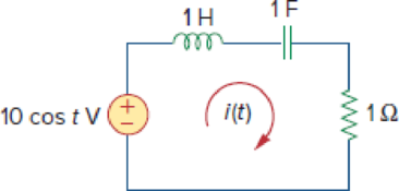
In the circuit of Fig. 10.46, current i(t) is:
- (a) 10 cos t A
- (b) 10 sin t A
- (c) 5 cos t A
- (d) 5 sin t A
- (e) 4.472 cos(t – 63.43°) A
Figure 10.46
For Review Question 10.4.
Expert Solution & Answer
Want to see the full answer?
Check out a sample textbook solution
Students have asked these similar questions
For the circuit shown in Fig. 10.107, find the Norton
equivalent circuit at terminals a-b.
60 Q
40 Q
3/60° A
o a
bo
j80 N
-j30 Q
ll
Figure 1090 For Prob. 1047. 10.48 Find i, in the circuit in Fig. 10.91 y superposition. A 10.: in the 50 cos 20007 V 0s(2t - 60°) V 2 sin 40001 A 10.5 Figure 1091 o
2 If Is-60mA, nd all unknown currents
e 10:39
Electrical Circuit Analysis Lab.
2.5 N
102
25 2
150
30 2
Chapter 10 Solutions
Fundamentals of Electric Circuits
Ch. 10.2 - Using nodal analysis, find v1 and v2 is in the...Ch. 10.2 - Calculate V1 and V2 in the circuit shown in Fig....Ch. 10.3 - Find Io in Fig. 10.8 using mesh analysis. Figure...Ch. 10.3 - Figure 10.11 For Practice Prob. 10.4. Calculate...Ch. 10.4 - Find current Io in the circuit of Fig. 10.8 using...Ch. 10.4 - Calculate vo in the circuit of Fig. 10.15 using...Ch. 10.6 - Determine the Norton equivalent of the circuit in...Ch. 10.7 - Find vo and io in the op amp circuit of Fig....Ch. 10.7 - Obtain the closed-loop gain and phase shift for...Ch. 10.8 - Use PSpice to obtain vo and io in the circuit of...
Ch. 10.8 - Obtain Vx and Ix in the circuit depicted in Fig....Ch. 10.9 - Determine the equivalent capacitance of the op amp...Ch. 10.9 - In the Wien-bridge oscillator circuit in Fig....Ch. 10 - The voltage Vo across the capacitor in Fig. 10.43...Ch. 10 - The value of the current Io in the circuit of Fig....Ch. 10 - Using nodal analysis, the value of Vo in the...Ch. 10 - In the circuit of Fig. 10.46, current i(t) is: (a)...Ch. 10 - Refer to the circuit in Fig. 10.47 and observe...Ch. 10 - For the circuit in Fig. 10.48, the Thevenin...Ch. 10 - In the circuit of Fig. 10.48, the Thevenin voltage...Ch. 10 - Refer to the circuit in Fig. 10.49. The Norton...Ch. 10 - Figure 10.49 For Review Questions 10.8 and 10.9....Ch. 10 - PSpice can handle a circuit with two independent...Ch. 10 - Determine i in the circuit of Fig. 10.50. Figure...Ch. 10 - Using Fig. 10.51, design a problem to help other...Ch. 10 - Determine vo in the circuit of Fig. 10.52. Figure...Ch. 10 - Compute vo(t) in the circuit of Fig. 10.53. Figure...Ch. 10 - Find io in the circuit of Fig. 10.54.Ch. 10 - Determine Vx in Fig. 10.55. Figure 10.55 For Prob....Ch. 10 - Use nodal analysis to find V in the circuit of...Ch. 10 - Use nodal analysis to find current io in the...Ch. 10 - Use nodal analysis to find vo in the circuit of...Ch. 10 - Use nodal analysis to find vo in the circuit of...Ch. 10 - Using nodal analysis, find io(t) in the circuit in...Ch. 10 - Using Fig. 10.61, design a problem to help other...Ch. 10 - Determine Vx in the circuit of Fig. 10.62 using...Ch. 10 - Calculate the voltage at nodes 1 and 2 in the...Ch. 10 - Solve for the current I in the circuit of Fig....Ch. 10 - Use nodal analysis to find Vx in the circuit shown...Ch. 10 - By nodal analysis, obtain current Io in the...Ch. 10 - Use nodal analysis to obtain Vo in the circuit of...Ch. 10 - Obtain Vo in Fig. 10.68 using nodal analysis.Ch. 10 - Refer to Fig. 10.69. If vs (t) = Vm sin t and vo...Ch. 10 - For each of the circuits in Fig. 10.70, find Vo/Vi...Ch. 10 - For the circuit in Fig. 10.71, determine Vo/Vs....Ch. 10 - Using nodal analysis obtain V in the circuit of...Ch. 10 - Design a problem to help other students better...Ch. 10 - Solve for io in Fig. 10.73 using mesh analysis....Ch. 10 - Use mesh analysis to find current io in the...Ch. 10 - Using mesh analysis, find I1 and I2 in the circuit...Ch. 10 - In the circuit of Fig. 10.76, determine the mesh...Ch. 10 - Using Fig. 10.77, design a problem help other...Ch. 10 - Use mesh analysis to find vo in the circuit of...Ch. 10 - Use mesh analysis to determine current Io in the...Ch. 10 - Determine Vo and Io in the circuit of Fig. 10.80...Ch. 10 - Compute I in Prob. 10.15 using mesh analysis....Ch. 10 - Use mesh analysis to find Io in Fig. 10.28 (for...Ch. 10 - Calculate Io in Fig. 10.30 (for Practice Prob....Ch. 10 - Compute Vo in the circuit of Fig. 10.81 using mesh...Ch. 10 - Use mesh analysis to find currents I1, I2, and I3...Ch. 10 - Using mesh analysis, obtain Io in the circuit...Ch. 10 - Find I1, I2, I3, and Ix in the circuit of Fig....Ch. 10 - Find io in the circuit shown in Fig. 10.85 using...Ch. 10 - Find vo for the circuit in Fig. 10.86, assuming...Ch. 10 - Using Fig. 10.87, design a problem to help other...Ch. 10 - Using the superposition principle, find ix in the...Ch. 10 - Use the superposition principle to obtain vx in...Ch. 10 - Use superposition to find i(t) in the circuit of...Ch. 10 - Solve for vo(t) in the circuit of Fig. 10.91 using...Ch. 10 - Determine io in the circuit of Fig. 10.92, using...Ch. 10 - Find io in the circuit of Fig. 10.93 using...Ch. 10 - Using source transformation, find i in the circuit...Ch. 10 - Using Fig. 10.95, design a problem to help other...Ch. 10 - Use source transformation to find Io in the...Ch. 10 - Use the concept of source transformation to find...Ch. 10 - Rework Prob. 10.7 using source transformation. Use...Ch. 10 - Find the Thevenin and Norton equivalent circuits...Ch. 10 - For each of the circuits in Fig. 10.99, obtain...Ch. 10 - Using Fig. 10.100, design a problem to help other...Ch. 10 - For the circuit depicted in Fig. 10.101, find the...Ch. 10 - Calculate the output impedance of the circuit...Ch. 10 - Find the Thevenin equivalent of the circuit in...Ch. 10 - Using Thevenins theorem, find vo in the circuit of...Ch. 10 - Obtain the Norton equivalent of the circuit...Ch. 10 - For the circuit shown in Fig. 10.107, find the...Ch. 10 - Using Fig. 10.108, design a problem to help other...Ch. 10 - At terminals a-b, obtain Thevenin and Norton...Ch. 10 - Find the Thevenin and Norton equivalent circuits...Ch. 10 - Find the Thevenin equivalent at terminals ab in...Ch. 10 - For the integrator shown in Fig. 10.112, obtain...Ch. 10 - Using Fig. 10.113, design a problem to help other...Ch. 10 - Find vo in the op amp circuit of Fig. 10.114....Ch. 10 - Compute io(t) in the op amp circuit in Fig. 10.115...Ch. 10 - If the input impedance is defined as Zin = Vs/Is,...Ch. 10 - Evaluate the voltage gain Av = Vo/Vs in the op amp...Ch. 10 - In the op amp circuit of Fig. 10.118, find the...Ch. 10 - Determine Vo and Io in the op amp circuit of Fig....Ch. 10 - Compute the closed-loop gain Vo/Vs for the op amp...Ch. 10 - Determine vo(t) in the op amp circuit in Fig....Ch. 10 - For the op amp circuit in Fig. 10.122, obtain Vo....Ch. 10 - Obtain vo(t) for the op amp circuit in Fig. 10.123...Ch. 10 - Use PSpice or MultiSim to determine Vo in the...Ch. 10 - Solve Prob. 10.19 using PSpice or MultiSim. Obtain...Ch. 10 - Use PSpice or MultiSim to find vo(t) in the...Ch. 10 - Obtain Vo in the circuit of Fig. 10.126 using...Ch. 10 - Using Fig. 10.127, design a problem to help other...Ch. 10 - Use PSpice or MultiSim to find V1, V2, and V3 in...Ch. 10 - Determine V1, V2, and V3 in the circuit of Fig....Ch. 10 - Use PSpice or MultiSim to find vo and io in the...Ch. 10 - The op amp circuit in Fig. 10.131 is called an...Ch. 10 - Figure 10.132 shows a Wien-bridge network. Show...Ch. 10 - Consider the oscillator in Fig. 10.133. (a)...Ch. 10 - The oscillator circuit in Fig. 10.134 uses an...Ch. 10 - Figure 10.135 shows a Colpitts oscillator. Show...Ch. 10 - Design a Colpitts oscillator that will operate at...Ch. 10 - Figure 10.136 shows a Hartley oscillator. Show...Ch. 10 - Refer to the oscillator in Fig. 10.137. (a) Show...
Knowledge Booster


Learn more about
Need a deep-dive on the concept behind this application? Look no further. Learn more about this topic, electrical-engineering and related others by exploring similar questions and additional content below.Similar questions
- Consider the system below. For this question, let C (s) = K, in this question K is a positive real number. a) Prove that if the root locus of the system is drawn, the points s1,2=−0.3214 ± 2.8951j will be on the curve. (Show it by doing mathematical calculation without drawing the curve.) b) Draw the root locus of the system. c) It is desired that the dominant (= near the imaginary axis) poles of the closed loop system be at the points s1,2= −0.3214 ± 2.8951j. What should K be for this? What can be said about the stability of the closed loop system for this K value? d) What are the unit step, ramp and parabolic reference tracking errors of the system for K in the option c?arrow_forwardDetermine I(t) in the circuit below. 10√/2 sin (10t) 2.076 cos (10t+4.764°) A 2.076 cos (10t + 85.236°) A O 2.935 cos (10t - 85.236°) A 2.935 sin (10t4.764°) A Select one: +1 0.2H vs (t) I (t) 1 120 F m 6Ωarrow_forwardProblem 10.003 - Nodal analysis in circuits with voltage sources Calculate the output voltage vo(t) of the circuit given below, where i(t) = 3 cos 4t A. Please report your answer so the magnitude is positive and all angles are in the range of negative 180 degrees to positive 180 degrees. 492 2 H 16 sin 4t V + + Vo 1/22 F 192 The output voltage of the circuit is vo(t) www 6Ω ✓✔ (Click to select) t+ sin COS °)) V.arrow_forward
- 10:45 1 .III 5G Done Series Parallel Practice Problems 1 of 7 Series/Parallel Circuits Practice Problems For each circuit provided, fully solve and complete the associated table. 1. 12 GOV RS 2000 R4 3000 R3 350 R(Q) V(v) I(A) P(W) 22222 300 300 35 15 200 Total R(Q) V(v) I(A) P(W)arrow_forward(ACADEMIC) 8205828page%3D1 The equivalent resistance RAR (in the figure) is: A O 62. 10. BO 10. 12. b. not possible to compute without Y to Delta conversion. C. bere to search S3一4arrow_forward10.) Find Req 10 N 10 Ω Rea 10 Narrow_forward
- 10:55 BYV 2.00 Yo 49 (48) KB/S Two coils are A and B ar : Editing 9/7/21 10:55 AM Two coils are A and B are connected in series to a supply of 230V, 50HZ. Coil A has an inductance of 0.2H and a resistance of 20 Q, and coil B has an inductance of 0.05H and a resistance of 60 Q. Calculate the current and its phase angle relative to the supply voltage. Also determine the voltage across each coil. |arrow_forward98% @ au 18 uaJI 10:48 4 s 4 1440 docs.google.com/forms A bla 10 Q1: As the figure Shawn for t=O, switch 1 is closed and switch 2 is closed 4sec later, find i(t) for * t>O and i for t=2s, and t35s ww S2 ww A OF HS i(i(t)={(0 ts0, 4(1-e^(-2t) ) Osts4, 2.727+1.273e^(-1.466(t-4) t24) )}A ,3.93A, 3.022A i(i(t)={(0 ts0, 4(1-e^(-2t) ) Osts4, 2.727+1.273e^(-1.466(t-4) t24) )}A ,3.93A, 4.022A i(i(t)={(0 ts0, 4(1-e^(-2t) ) Osts4, 2.727+1.273e^(-1.466(t-4) t24) )}A ,2.93A, 3.022A None of them 10:35 AM is parrow_forwardCalculate current of inductor and voltage of capacitor in transient state after turning on the switch in the circuit of Fig. 10.25. Assume: R=5Ω, C=100μF, L=1H, e1(t)=10V, e2(t)=10V.arrow_forward
- b) Find the Node voltage at point "a". Give the answer as a function of time Va(t) = ? Note: Be careful about the terminal signs. 09 + e 2000s (1006) V 10 sin (100t+15°V -5+j2 V -10 236° Varrow_forwardS:41) A circuit consists of a current source, Is = 43 sin(5386t - 40.29 °) mA in parallel with a 72 kΩ resistor and a 2895 pF capacitor. Determine the magnitude of the effective value of current that flows through the resistor.arrow_forward10.23. Draw the block diagrams of both the direct forms I and II simulation diagrams for the systems with the following difference equations: (a) 2y[n]y[n 1] + 4y[n-2] = 5x[n] (b) 1 3]arrow_forward
arrow_back_ios
SEE MORE QUESTIONS
arrow_forward_ios
Recommended textbooks for you
 Introductory Circuit Analysis (13th Edition)Electrical EngineeringISBN:9780133923605Author:Robert L. BoylestadPublisher:PEARSON
 Delmar's Standard Textbook Of ElectricityElectrical EngineeringISBN:9781337900348Author:Stephen L. HermanPublisher:Cengage Learning
 Programmable Logic ControllersElectrical EngineeringISBN:9780073373843Author:Frank D. PetruzellaPublisher:McGraw-Hill Education
 Fundamentals of Electric CircuitsElectrical EngineeringISBN:9780078028229Author:Charles K Alexander, Matthew SadikuPublisher:McGraw-Hill Education
 Electric Circuits. (11th Edition)Electrical EngineeringISBN:9780134746968Author:James W. Nilsson, Susan RiedelPublisher:PEARSON
 Engineering ElectromagneticsElectrical EngineeringISBN:9780078028151Author:Hayt, William H. (william Hart), Jr, BUCK, John A.Publisher:Mcgraw-hill Education,
Introductory Circuit Analysis (13th Edition)
Electrical Engineering
ISBN:9780133923605
Author:Robert L. Boylestad
Publisher:PEARSON
Delmar's Standard Textbook Of Electricity
Electrical Engineering
ISBN:9781337900348
Author:Stephen L. Herman
Publisher:Cengage Learning
Programmable Logic Controllers
Electrical Engineering
ISBN:9780073373843
Author:Frank D. Petruzella
Publisher:McGraw-Hill Education
Fundamentals of Electric Circuits
Electrical Engineering
ISBN:9780078028229
Author:Charles K Alexander, Matthew Sadiku
Publisher:McGraw-Hill Education
Electric Circuits. (11th Edition)
Electrical Engineering
ISBN:9780134746968
Author:James W. Nilsson, Susan Riedel
Publisher:PEARSON
Engineering Electromagnetics
Electrical Engineering
ISBN:9780078028151
Author:Hayt, William H. (william Hart), Jr, BUCK, John A.
Publisher:Mcgraw-hill Education,
Routh Hurwitz Stability Criterion Basic Worked Example; Author: The Complete Guide to Everything;https://www.youtube.com/watch?v=CzzsR5FT-8U;License: Standard Youtube License