
Concept explainers
Videos
Use the superposition principle to obtain vx in the circuit of Fig. 10.89. Let vs = 50 sin 2t V and is = 12 cos(6t + 10°) A.
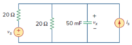
Figure 10.89
Calculate the voltage
Answer to Problem 44P
The value of voltage
Explanation of Solution
Given data:
Refer to Figure 10.89 in the textbook.
Formula used:
Write the expression to calculate impedance of the capacitor.
Here,
Write the general representation of sinusoidal sine function.
Here,
Write the general expression to phasor transform of sinusoidal function from time domain to frequency domain.
Here,
Write the polar form representation of frequency domain.
Write the general representation of sinusoidal cosine function.
Here,
Write the general expression to phasor transform of sinusoidal function from time domain to frequency domain.
Here,
Write the polar form representation of frequency domain.
Calculation:
Let
Comparing
Substitute
Substitute
To find
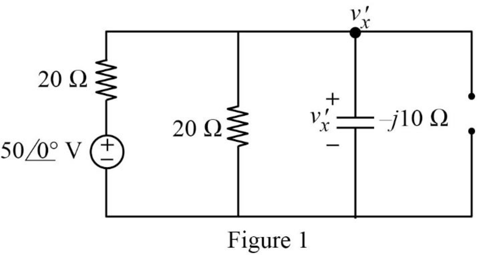
In Figure 1, apply Kirchhoff’s current law at node
Simplify the above equation as follows.
Represent the voltage
Comparing
Substitute
Substitute
To find
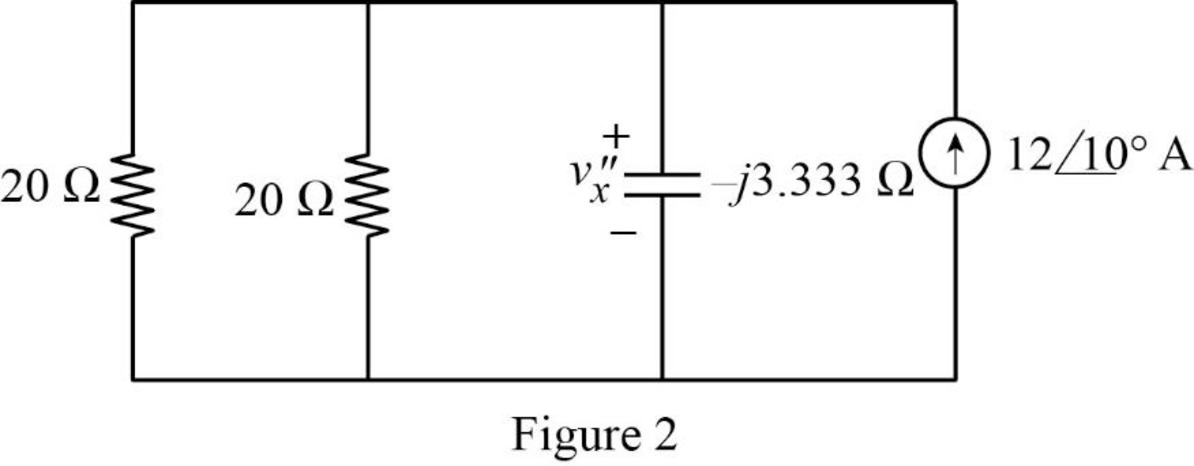
In Figure 2, reduce the parallel combination of
The reduced circuit is as shown in Figure 3.
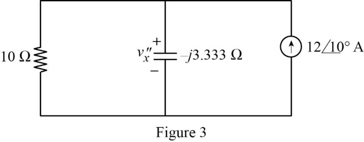
From Figure 3, write the expression for voltage
Represent the voltage
Write the expression for current
Substitute
Conclusion:
Thus, the value of voltage
Want to see more full solutions like this?
Chapter 10 Solutions
Fundamentals of Electric Circuits
Additional Engineering Textbook Solutions
Electronics Fundamentals: Circuits, Devices & Applications
Electric machinery fundamentals
Engineering Electromagnetics
ANALYSIS+DESIGN OF LINEAR CIRCUITS(LL)
Electric Circuits (10th Edition)
Programmable Logic Controllers


- 10. A circuit is made up of 10 Q resistance, 12 mH inductance and 281.5 µF capacitance in series. The supply voltage is 100 V (constant). Calculate the value of the current when the supply frequency is (a) 50 Hz and (b) 150 Hz.arrow_forwardA circuit branch is found to have an equivalent impedance of Z=120−j45Ω. It is given that this impedance is a series combination of a 120Ω resistor and another passive component. Which of the following is most likely to be the second component?a) Inductorb) Capacitorc) Not enough information to determine the componentarrow_forward15 Find i for the circuit shown in Fig. 10-19. HH 0.001 μF 10 cos 106t V +21 500 Ω Fig. 10-19 See Prob. 5. 12+ 10 cos 2 x 10⁶arrow_forward
- 10:55 BYV 2.00 Yo 49 (48) KB/S Two coils are A and B ar : Editing 9/7/21 10:55 AM Two coils are A and B are connected in series to a supply of 230V, 50HZ. Coil A has an inductance of 0.2H and a resistance of 20 Q, and coil B has an inductance of 0.05H and a resistance of 60 Q. Calculate the current and its phase angle relative to the supply voltage. Also determine the voltage across each coil. |arrow_forward2 If Is-60mA, nd all unknown currents e 10:39 Electrical Circuit Analysis Lab. 2.5 N 102 25 2 150 30 2arrow_forwardC/ Find the 10-point DFT of the sequence: √x(n)= cos (n). sin (n)arrow_forward
- A coil with impedance 8+j6 Ω is connected in series with a capacitive reactance X. The series combination is connected in parallel with a resistor R. Given that the equivalent impedance of the resulting circuit is 2.5∠0°Ω, find the value of X and R.arrow_forward4. Find the phasors corresponding to the following a. v(t) = 21 cos(4t – 15°)V b. i(t) = -8 sin(10t + 70°) mA Sha Erro The 'api. Rec http:arrow_forwardQ1; Vcos(wt) Vm=5V 1 + Calculate vc (3.54V, -45 deg) R 1.5 KQ ΚΩ ww i(t) C: 0.1 μF w=6660 rad/s (f=1060 Hz. T = 0.943 ms) + vc(t) Iarrow_forward
- Solve the following for ALL circuits. Show the summary of your answers at the end of each problem. All answers should be in polar form! a. Total Current b. Individual Currents c. Individual Voltages d. True/Real power e. Reactive power f. Apparent power 1. Circuit 1 (freq=200 Hz) 10 K www 10 COSwt 100 100 LA HE 10 pFarrow_forward15 Find i for the circuit shown in Fig. 10-19. H 0.001 F +6 10 cos 106 V www 500 2 Fig. 10-19 See Prob. 5. J 12+ 10 cos 2 x 10⁶arrow_forward1- The impedance of a capacitor increases with increasing frequency. (a) True (b) False 2- If the load impedance is 20-j20, the power factor is (a) -45° (b) 0 (c) 1 (d) 0.7071 (e) none of these 3- A series RL circuit has VR = 10 V and VL = 6 V. The supply voltage is: (a) -4 V (b) 4 V (c) 11.66 V (d) 16 V is: 4- In the power triangle shown in Fig. 1(a), the reactive power (a) 1000 VAR leading (c) 866 VAR leading (b) 1000 VAR lagging (d) 866 VAR lagging 5- For the power triangle in Fig.1(b), the apparent power is: (a) 2000 VA (c) 866 VAR (b) 1000 VAR (d) 500 VAR 60⁰ 500 W (a) Fig.1 30⁰ (b) 1000 VARarrow_forward
 Introductory Circuit Analysis (13th Edition)Electrical EngineeringISBN:9780133923605Author:Robert L. BoylestadPublisher:PEARSON
 Delmar's Standard Textbook Of ElectricityElectrical EngineeringISBN:9781337900348Author:Stephen L. HermanPublisher:Cengage Learning
 Programmable Logic ControllersElectrical EngineeringISBN:9780073373843Author:Frank D. PetruzellaPublisher:McGraw-Hill Education
 Fundamentals of Electric CircuitsElectrical EngineeringISBN:9780078028229Author:Charles K Alexander, Matthew SadikuPublisher:McGraw-Hill Education
 Electric Circuits. (11th Edition)Electrical EngineeringISBN:9780134746968Author:James W. Nilsson, Susan RiedelPublisher:PEARSON
 Engineering ElectromagneticsElectrical EngineeringISBN:9780078028151Author:Hayt, William H. (william Hart), Jr, BUCK, John A.Publisher:Mcgraw-hill Education,