
Introductory Circuit Analysis (13th Edition)
13th Edition
ISBN: 9780133923605
Author: Robert L. Boylestad
Publisher: PEARSON
expand_more
expand_more
format_list_bulleted
Related questions
Concept explainers
Question
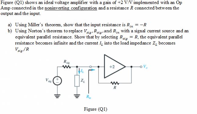

Transcribed Image Text:Figure (Q1) shows an ideal voltage amplifier with a gain of +2 V/V implemented with an Op
Amp connected in the noninverting configuration and a resistance R connected between the
output and the input.
a) Using Miller's theorem, show that the input resistance is Rn = -R
b) Using Norton's theorem to replace Vig, Rig and Rin with a signal current source and an
equivalent parallel resistance. Show that by selecting Rig = R, the equivalent parallel
resistance becomes infinite and the current I, into the load impedance Z, becomes
Vrig /R
Rig
+2
Vas
R
R
Figure (Q1)
Expert Solution
This question has been solved!
Explore an expertly crafted, step-by-step solution for a thorough understanding of key concepts.

This is a popular solution

Trending nowThis is a popular solution!

Step by stepSolved in 2 steps with 2 images

Knowledge Booster


Learn more about
Need a deep-dive on the concept behind this application? Look no further. Learn more about this topic, electrical-engineering and related others by exploring similar questions and additional content below.Similar questions
- An op-amp has a unity-gain frequency (funity) of 12MHz. What is the amplifier's bandwidth, in kHz, when ACL = 536?arrow_forwardDraw the circuit diagram of the basic noninverting amplifier configuration. Give an expression for the closed-loop voltage gain of the circuit in terms of the resistances, assuming an ideal op amp. Give expressions for the input impedance and output impedance of the circuit.arrow_forwardThe ideal op-amps depicted can swing rail-to-rail at output, and Vcc= 13 V. Initially, the output voltage Vo = +13 V and the input voltage is vS = -13 V. The feedback resistors are R1 = 6.4 k0, R2 = 8.5 kQ, and R3 = 1.6 KQ. If the input voltage is gradually increased, at what value of vS (to 1% accuracy) does the output voltage (Vo) change to Vo=-Vcc? VVV vS = + R10 Vcc -Vcc R20 04 O Voarrow_forward
- 2. One of the earliest uses of operational amplifiers (OPAMPS) is to perform mathematical operations on analog signals. Of the two OPAMP circuits shown below, one of them is known as an analog differentiator while the other an analog integrator. Analyse these circuits to discover why by finding an equation for their output VOUT in terms of their time-varying input VIN(t). (You may assume the OPAMPS are ideal.) VIN(t) RF Circuit A ☑ RF VOUT VIN(t) Circuit B VOUTarrow_forward= Make a inverting op amp to have a voltage gain of -5 with an R, 2 kn. You must ensure that the output does not exceed +12 V. a. Specify the value of Rf and the supply voltages +Vcc. Vs b. For this circuit, what is the range of the source voltage, vº, to ensure that the op amp remains linear? + Rs Rf +Vcc -Vcc + Voarrow_forward(Q1) Design a circuit with Op-Amp when Vi 3v and Vo = 12v (i) Using Inverting Amplifier (ii) Using Non-Inverting Amplifier Assume any value if necessary.arrow_forward
arrow_back_ios
arrow_forward_ios
Recommended textbooks for you
- Introductory Circuit Analysis (13th Edition)Electrical EngineeringISBN:9780133923605Author:Robert L. BoylestadPublisher:PEARSON
 Delmar's Standard Textbook Of ElectricityElectrical EngineeringISBN:9781337900348Author:Stephen L. HermanPublisher:Cengage Learning
 Programmable Logic ControllersElectrical EngineeringISBN:9780073373843Author:Frank D. PetruzellaPublisher:McGraw-Hill Education
  Fundamentals of Electric CircuitsElectrical EngineeringISBN:9780078028229Author:Charles K Alexander, Matthew SadikuPublisher:McGraw-Hill Education
 Electric Circuits. (11th Edition)Electrical EngineeringISBN:9780134746968Author:James W. Nilsson, Susan RiedelPublisher:PEARSON
 Engineering ElectromagneticsElectrical EngineeringISBN:9780078028151Author:Hayt, William H. (william Hart), Jr, BUCK, John A.Publisher:Mcgraw-hill Education,
Introductory Circuit Analysis (13th Edition)
Electrical Engineering
ISBN:9780133923605
Author:Robert L. Boylestad
Publisher:PEARSON
Delmar's Standard Textbook Of Electricity
Electrical Engineering
ISBN:9781337900348
Author:Stephen L. Herman
Publisher:Cengage Learning
Programmable Logic Controllers
Electrical Engineering
ISBN:9780073373843
Author:Frank D. Petruzella
Publisher:McGraw-Hill Education
Fundamentals of Electric Circuits
Electrical Engineering
ISBN:9780078028229
Author:Charles K Alexander, Matthew Sadiku
Publisher:McGraw-Hill Education
Electric Circuits. (11th Edition)
Electrical Engineering
ISBN:9780134746968
Author:James W. Nilsson, Susan Riedel
Publisher:PEARSON
Engineering Electromagnetics
Electrical Engineering
ISBN:9780078028151
Author:Hayt, William H. (william Hart), Jr, BUCK, John A.
Publisher:Mcgraw-hill Education,